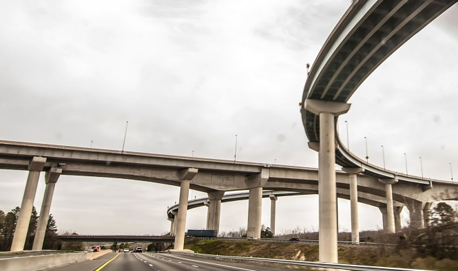
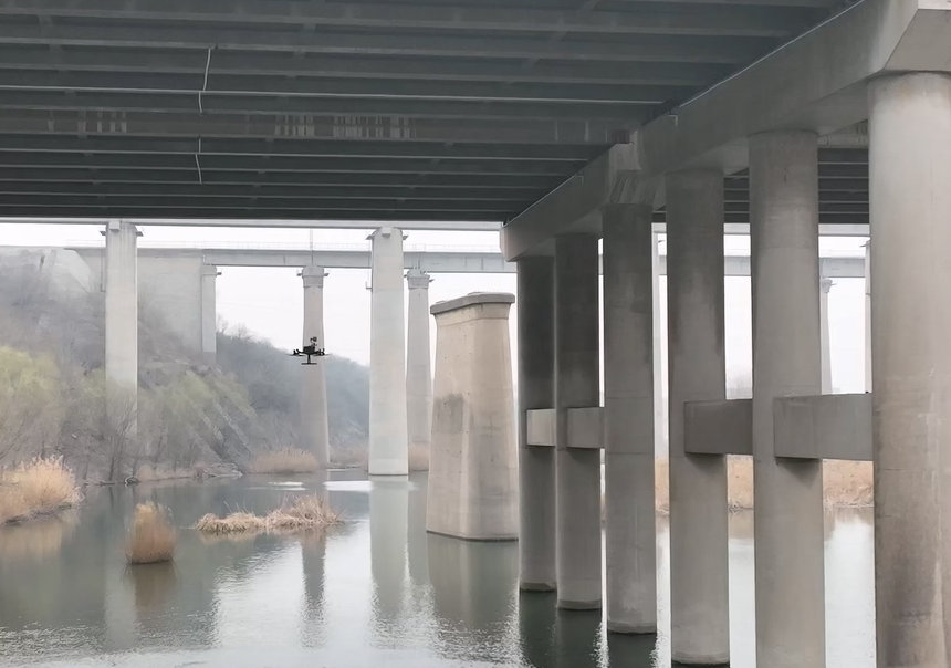
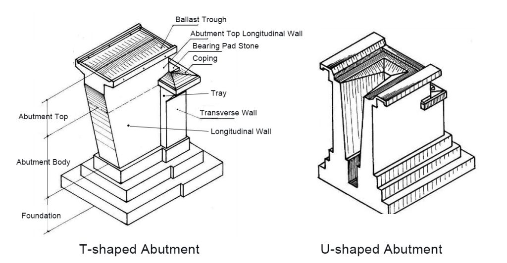
U-shaped bridge abutments are widely adopted in modern bridge construction for their compact form and good lateral stability. They function as the transition structure between the superstructure and the subgrade, resisting horizontal earth pressure and supporting the end spans.
However, due to complex stress conditions, variable foundation properties, and construction deviations, U-shaped abutments are prone to various structural and geotechnical issues. This article presents a detailed technical analysis of typical damage types, their causes, and corresponding preventive measures.
1. Tilting of the Abutment
(1) Causes
Abutment tilting is primarily caused by uneven foundation settlement, unbalanced lateral earth pressure, or insufficient stiffness of the structure. When the backfill on one side is inadequately compacted, differential settlement occurs, causing the abutment to rotate or lean toward the bridge span. Poor drainage or excessive pore water pressure can further aggravate the displacement.
(2) Damage Characteristics
- Lateral displacement of the abutment top toward the bridge span.
- Visible cracks at the junction between the abutment and the wing walls.
- Joint misalignment and surface unevenness of the bridge deck.
(3) Preventive and Treatment Measures
- Reinforce the foundation through soil stabilization or grouting before construction.
- Ensure uniform and layered compaction of backfill, controlling moisture content.
- Improve the drainage system to prevent water accumulation behind the abutment.
- Use flexible connections or expansion joints between the abutment and the superstructure to reduce stress concentration.
2. Deformation of Front and Side Walls
(1) Causes
The front and side walls of a U-shaped abutment retain backfill soil and are constantly subjected to horizontal earth pressure. When the compaction of backfill is uneven or the drainage system fails, unbalanced lateral pressure builds up. Weak foundations, improper design of wall thickness, or inadequate reinforcement detailing can cause outward tilting or bulging.
(2) Damage Characteristics
- Outward inclination or bulging of the side walls.
- Cracks developing along the base or near the corners of the front wall.
- Separation between the wall and abutment cap, sometimes leading to leakage paths for rainwater.
(3) Preventive and Treatment Measures
- Strictly control backfill quality and compaction along both sides of the abutment.
- Provide weep holes or vertical drains to release hydrostatic pressure.
- Increase the wall’s rigidity or install internal tie beams or anchor rods for lateral stability.
- Apply concrete jacketing or shotcrete reinforcement when deformation is minor and progressive.
3. Foundation and Base Damage
(1) Causes
Foundation problems stem from insufficient bearing capacity, differential settlement, or erosion by groundwater. In soft soil areas, the bearing pressure under the abutment may exceed the soil’s allowable strength, resulting in uneven settlement or rotation. Poorly designed drainage or blocked filters may also increase pore water pressure, accelerating soil softening.
(2) Damage Characteristics
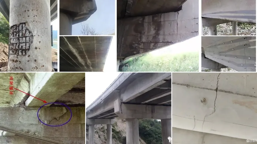
- Vertical or inclined cracks in the abutment body.
- Differential settlement between abutment and approach slab.
- Tilting of the entire abutment structure or uneven deformation of the wing walls.
(3) Preventive and Treatment Measures
- Conduct detailed geological surveys and bearing capacity tests before construction.
- Strengthen the foundation by grouting, replacement of soft soil, or installing drainage consolidation layers.
- Where groundwater levels fluctuate significantly, use cutoff walls or subsurface drainage to control uplift pressure.
- In operation, continuous monitoring of settlement data can help identify potential instability at an early stage.
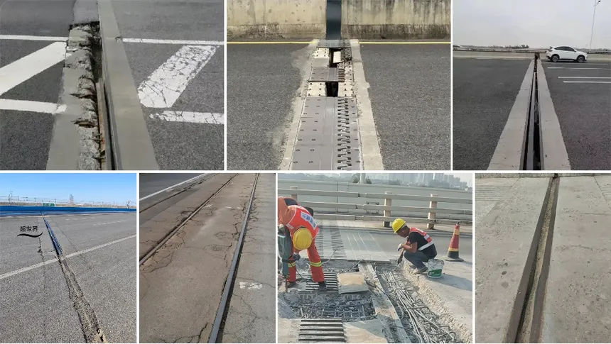
4. Abutment Cap and Expansion Joint Damage
(1) Causes
The abutment cap bears loads from the superstructure and transfers them to the abutment body. Temperature variations, vehicle loads, and poor joint sealing can lead to cracking of the cap and damage to expansion joints. If the bearing seat is uneven, the vertical load becomes eccentric, intensifying cap stress.
(2) Damage Characteristics
- Longitudinal or transverse cracks along the abutment cap.
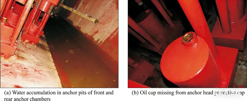
- Water infiltration through failed joint sealants.
- Rusting or spalling of reinforcement due to long-term moisture exposure.
(3) Preventive and Treatment Measures
- Use high-quality waterproofing sealant and flexible joint materials.
- Ensure that bearings are properly leveled and free of debris.
- Apply epoxy injection or polymer mortar repair for minor cracks.
- For severe damage, replace the cap or install a secondary bearing beam.
5. Other Common Issues
(1) Design and Construction Deviations
Improper layout, insufficient reinforcement anchorage, or poor concrete quality often lead to early cracking and uneven stress distribution.
(2) Environmental Impacts
- Freeze–thaw cycles in cold regions cause surface spalling and internal microcracks.
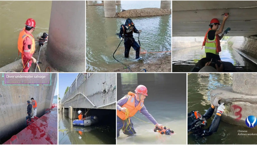
- Flooding and scouring can erode the foundation toe and reduce overall stability.
- Seismic effects may induce lateral displacement or separation at expansion joints.
(3) Preventive and Treatment Measures
- Apply corrosion-resistant reinforcement and protective coatings.
- Regularly inspect drainage outlets and slope protection near the abutment.
- Strengthen design details in seismic zones to improve ductility and energy dissipation.
6. Regular Inspection and Maintenance
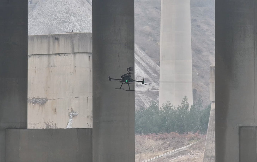
Bridge abutments are exposed to both structural and environmental stresses over their service life. Periodic inspection is essential to detect deformation, cracking, or drainage blockage early.
Traditional manual inspection methods can be limited by access and safety concerns.
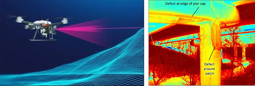
Modern UAV (drone) and AI-assisted inspection systems—such as those developed by Riebo—can capture high-resolution images of abutment surfaces, identify cracks or tilting through computer vision analysis, and provide digital documentation for maintenance decision-making.
These tools allow engineers to monitor abutment health continuously and take preventive action before structural risks escalate.
Conclusion
U-shaped abutments play a vital role in maintaining the structural continuity and stability of bridges. However, their complex load conditions make them susceptible to multiple forms of damage—tilting, wall deformation, foundation settlement, and cracking.
Effective control requires a combination of geotechnical improvement, structural reinforcement, proper drainage design, and long-term monitoring.
By integrating advanced inspection technologies like Riebo’s AI bridge inspection system, engineers can enhance detection accuracy, reduce maintenance costs, and ensure the long-term safety of bridge substructures.