1. Overview
1.1 Functions and Requirements of Bridge Bearings
Bridge bearings are key structural components installed between the superstructure and substructure of a bridge. Their primary roles are:
- Load transfer: To transmit all types of loads from the bridge deck — including dead load, live load, temperature effects, shrinkage, and creep — to the piers or abutments.
- Movement accommodation: To allow for rotations and displacements caused by live loads, temperature changes, and material deformation, ensuring the actual structural behavior matches the design assumptions.
- Design considerations: The selection of bearing type and specification depends on factors such as span length, reaction forces, structural height, movement direction and magnitude (unidirectional or multidirectional), as well as seismic and damping requirements.
1.2 Bearing Layout Principles
The layout of bridge bearings is mainly determined by the bridge type and deck width. Different bridge structures require specific arrangements:
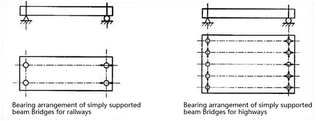
(1) Simply Supported Bridges
- Basic principle: One end is equipped with a fixed bearing, and the other end with a movable bearing.
- Railway bridges: Since the width is relatively small, lateral movement can be neglected, and usually only longitudinal movable bearings are installed.
- Highway bridges: The deck is wider, so lateral displacement should be considered, and corresponding movement capacity must be provided.
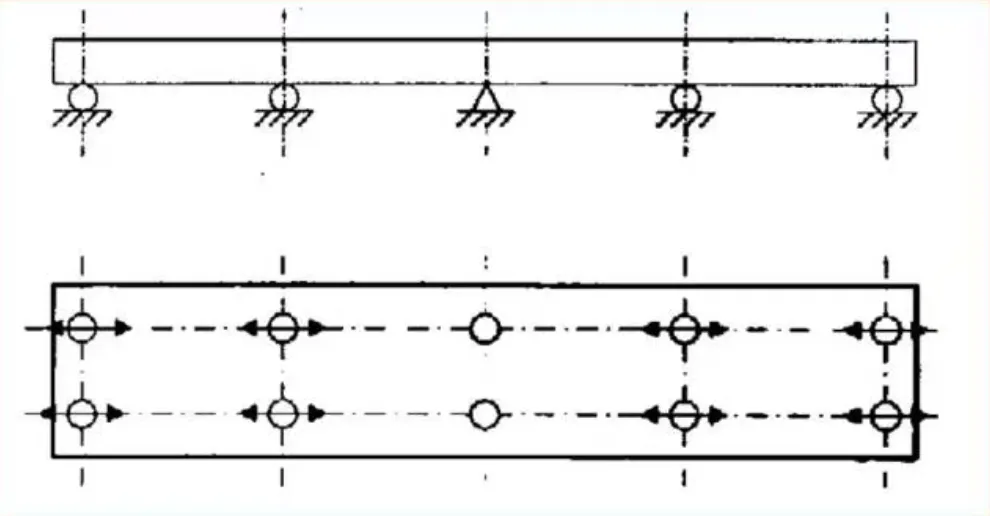
(2) Continuous Girder Bridges
- Each span group (between two expansion joints) should have one fixed bearing, preferably positioned near the middle pier of the span group.
- This prevents excessive expansion movement at the ends.
- If the middle pier is too tall, special measures should be taken to avoid excessive horizontal force on the pier top.
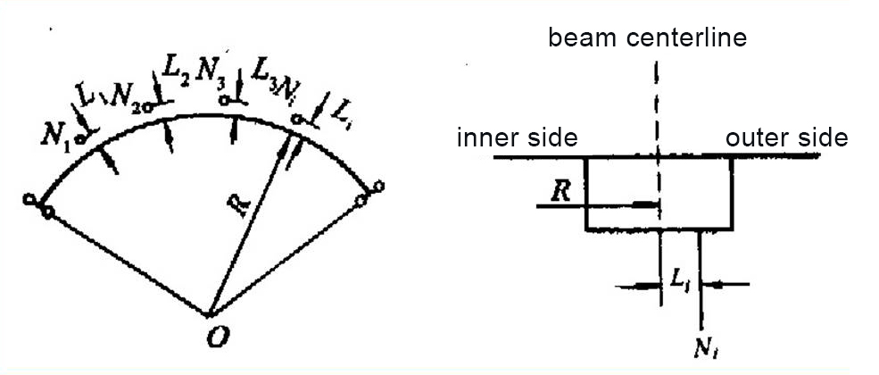
(3) Curved Continuous Bridges
- The bearing arrangement directly affects internal force distribution.
- Bearings must allow both longitudinal and transverse rotations.
- Typically, the central pier uses a single-point bearing, while the end piers or abutments use double bearings to resist torsion.
- Bearings may also be offset toward the outer curve to balance torque.
(4) Ramp and Sloped Bridges
- Ramp bridges: The fixed bearing is usually placed at the lower end so that the slope component of the load induces compression rather than tension at the lower edge of the girder.
- Level bridges: The fixed bearing is generally located at the forward end of the traffic direction.
(5) Installation Considerations
The bearing centerline must align with the superstructure’s support axis.
If long-term creep and shrinkage effects are expected, pre-alignment offsets can be introduced during installation.
2. Types and Structures of Bridge Bearings
2.1 Classification of Bearings
Bridge bearings can be categorized as follows:
- By material: Steel bearings, PTFE (polytetrafluoroethylene) bearings, rubber bearings, concrete bearings, and lead-core bearings.
- By deformation allowance: Fixed bearings, unidirectional movable bearings, and multidirectional movable bearings.
- By load capacity: Compression-only bearings and tension–compression bearings.
2.2 Structural Features of Common Bearing Types
(1) Simple Bearings
Made of multiple layers of bituminous felt or asbestos, with a compacted thickness not less than 1 cm. Suitable for slab bridges with spans less than 10 m.
(2) Steel Bearings
These rely on mechanical components (rolling, rocking, or sliding) to accommodate displacement and rotation. They offer high load capacity and are mainly used in railway bridges.
- Cast steel bearings: Manufactured from carbon or quality steel by molding and casting, and classified as flat plate, rocker, roller, or hinge types.
- Flat plate bearings: The simplest type, where fixed bearings are locked with steel pins and movable bearings have elongated holes for movement. Suitable only for small spans due to high friction.
-
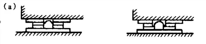
- Rocker bearings: Replace plane contact with curved contact to allow free rotation. They effectively transfer reaction forces but still have relatively high friction.
-
- Hinge (rocker pin) bearings: Composed of top plate, base plate, and a curved rocker; higher load capacity with increasing rocker diameter but also greater height.

-
- Roller bearings: Reaction forces are transferred through multiple rollers, providing uniform load distribution and reduced friction. Commonly used in large bridges.

- Modern steel bearings: Include stainless steel, sliding plate, and spherical bearings. They feature corrosion resistance, low maintenance, hardened contact surfaces, and minimal rotational resistance.
Spherical bearings combine a convex steel component with a PTFE plate for smooth, low-friction rotation.
(3) Rubber Bearings
- Laminated rubber bearings: Made of alternating rubber and steel plates. Available in rectangular or circular shapes, using chloroprene rubber (for temperatures ≥ –25 °C) or natural rubber (for –30 °C to –40 °C).
The bearings deform elastically in compression and shear to accommodate rotation and movement. They are widely used in highway and urban bridges with support reactions between 70–3600 kN.

- PTFE sliding rubber bearings: Add a PTFE sliding layer on top to reduce friction during horizontal displacement.
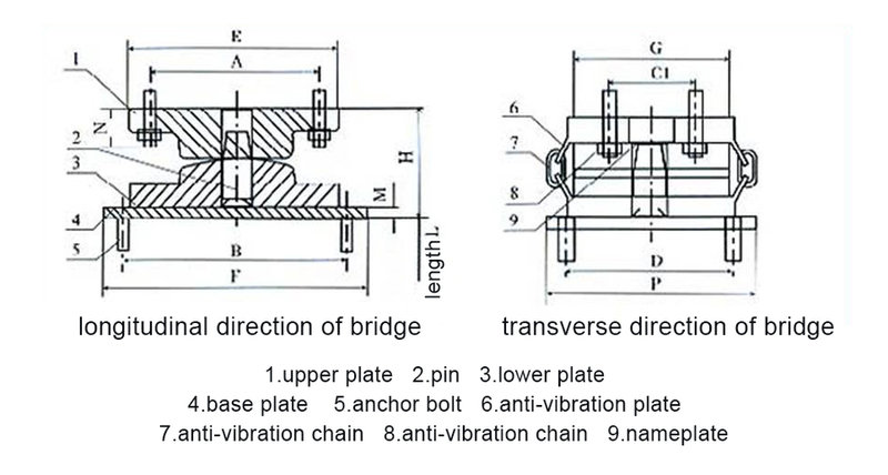
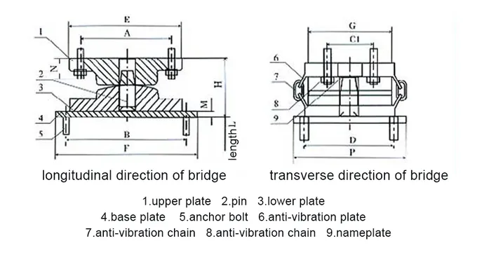
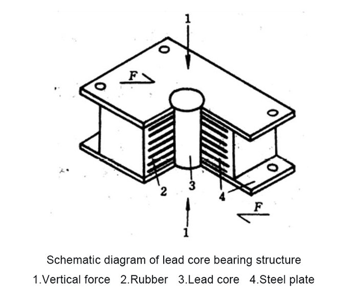
- Other variants: Spherical rubber bearings (for steep-slope bridges), inclined-type bearings, and lead-core rubber bearings for seismic energy dissipation.
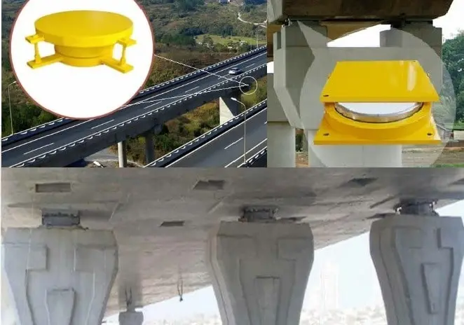
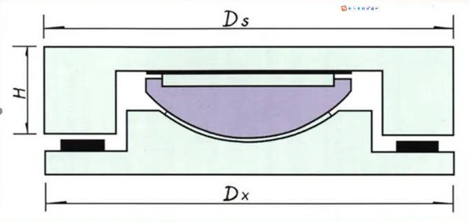
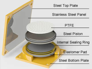
(4) Pot Bearings
Pot bearings combine steel components and confined rubber pads. They provide high vertical load capacity, large horizontal displacement, and excellent rotational flexibility. Typically used in large-span bridges where reactions exceed 1000 kN.
They are divided into fixed and movable types; movable pot bearings incorporate a PTFE sliding layer and an elastomeric compression pad, while fixed bearings restrict horizontal movement.
2.3 Bearing Selection Method
- By type:
Small and medium-span highway bridges generally use laminated rubber bearings.
Large-span or continuous beam bridges, as well as railway bridges, often adopt pot bearings. Some railway bridges still use steel bearings. - By load capacity:
The allowable bearing capacity must satisfy:- Nmax≤1.05[N]allowN_{\text{max}} \leq 1.05 [N]_{\text{allow}}Nmax≤1.05[N]allow
- Nmin≥0.8[N]allowN_{\text{min}} \geq 0.8 [N]_{\text{allow}}Nmin≥0.8[N]allow
to ensure proper pressure distribution and prevent frictional locking due to insufficient compression.
3. Design and Calculation of Bridge Bearings
3.1 Load Calculation
- When calculating support reactions under vehicle loads, dynamic impact factors must be included.
- If uplift forces are possible, both the maximum vertical force and uplift must be computed.
- Straight bridges consider longitudinal forces only; skewed or curved bridges also include transverse forces caused by centrifugal and wind loads.
- Braking forces depend on the number of lanes and applicable design codes; movable bearings should not transfer more horizontal force than their frictional resistance allows.
- In seismic zones, earthquake loads must be calculated and combined according to design seismic intensity requirements.
3.2 Design Calculation of Laminated Rubber Bearings
(1) Bearing Area Check:
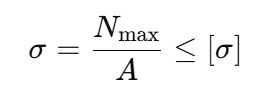
where
σ: actual compressive stress
: maximum reaction force
A: bearing plan area
[σ]: allowable compressive stress.
(2) Bearing Height and Shear Deformation:
To accommodate horizontal displacement through shear deformation of rubber layers:

where
Δ: total horizontal displacement
∑t: total rubber thickness
[tanγ]: allowable shear angle tangent.
(3) Rotation and Compression Check:
The bearing must remain in full contact under girder rotation. Average compression and deformation differences at the edges should meet code limits to prevent partial loading.
(4) Anti-Slip Verification:
Frictional resistance between the bearing and contact surfaces must resist applied horizontal forces.
Typical friction coefficients:
- Rubber–concrete: 0.3
- Rubber–steel: 0.2
Conclusion
Bridge bearings are essential to ensure structural stability and serviceability. From simple rubber pads to advanced pot and spherical bearings, proper selection, design, and installation are critical for long-term bridge performance.
Understanding bearing behavior, load paths, and deformation compatibility enables safer, more durable bridge structures.