Reinforced concrete simply supported beam bridges are widely used in highway, railway, and urban road construction due to their simple structure, convenient construction, and controllable cost. However, under the combined effects of design flaws, construction deviations, environmental corrosion, and long-term loading, these bridges are prone to various forms of deterioration. Scientific maintenance and repair strategies are therefore essential to extend their service life. This article systematically summarizes the common defect types and causes of reinforced concrete simply supported bridges and proposes targeted maintenance and repair methods.
I. Common Defects and Causes
(1) Surface Defects
Surface defects are the most visible form of deterioration, directly affecting both the appearance and the integrity of the protective concrete layer. Common types include:
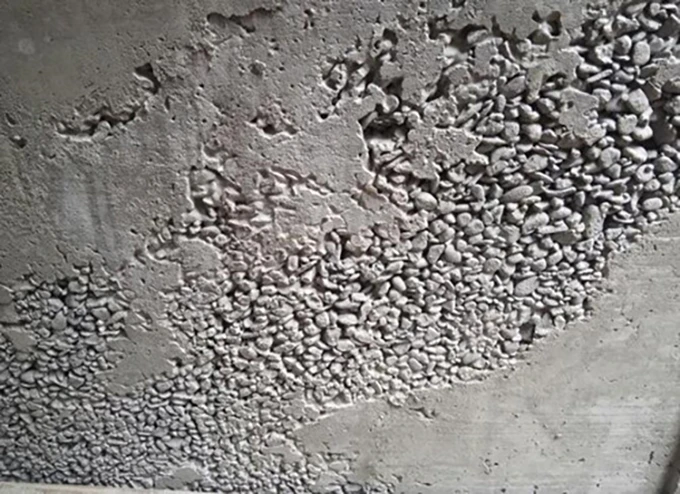
Honeycombing: Usually caused by insufficient vibration during concrete pouring, improper vibrator insertion depth, or overly large spacing between vibration points, resulting in trapped air pockets. Segregation during long-distance transportation or excessive drop height, as well as poorly sealed formwork joints causing mortar leakage, also contribute. Overly dense rebar placement or mismatched aggregate size can obstruct concrete flow, forming localized honeycomb defects.
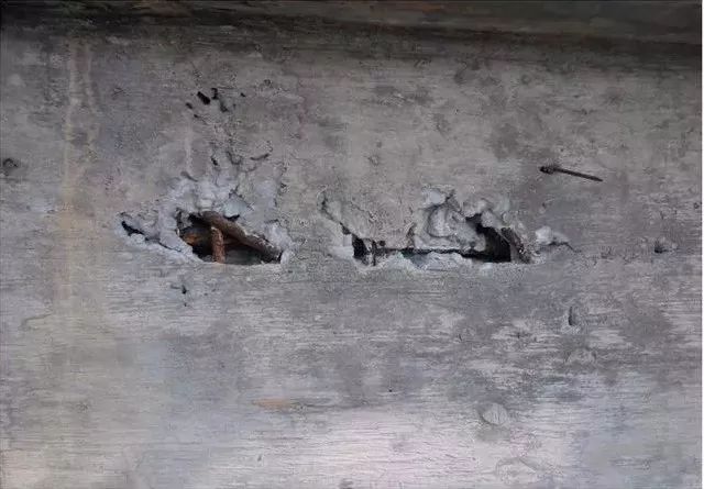
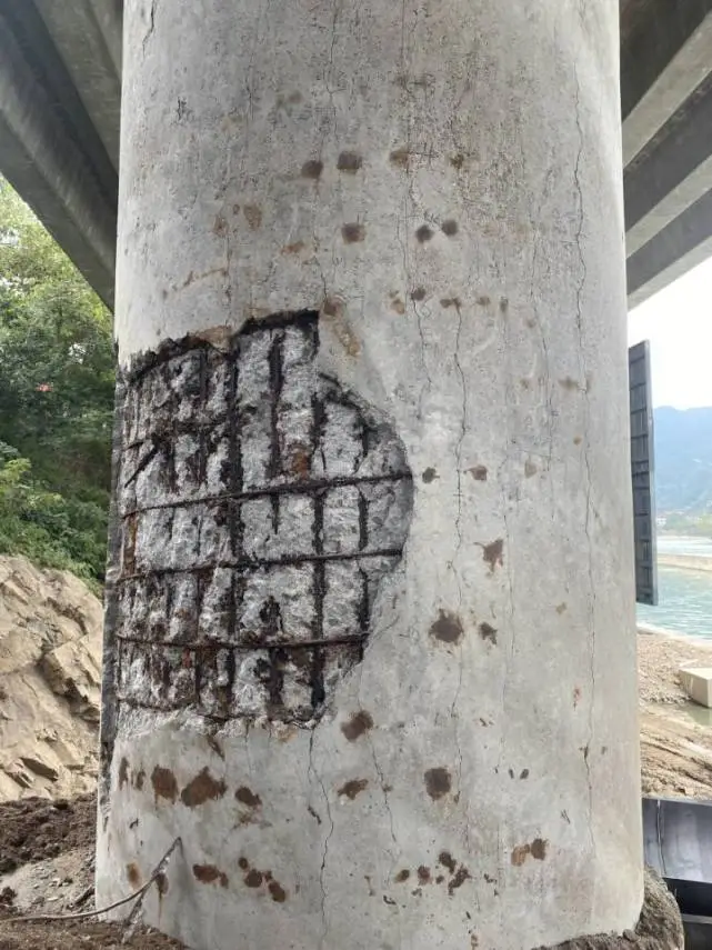
Exposed Reinforcement: If cover blocks are poorly fixed or insufficient in number, rebars may touch the formwork directly. Inadequate vibration then leads to loose mortar around the reinforcement. Over time, water ingress and corrosion expand the steel, exerting pressure that cracks and peels the surface concrete, exposing reinforcement.
Bugholes (Surface Roughness): Caused by uncleaned or rusted formwork, uneven or missing release agent, and insufficient pre-wetting of the formwork. The dry surface absorbs moisture and cement paste from fresh concrete, reducing surface strength and forming pitted defects.
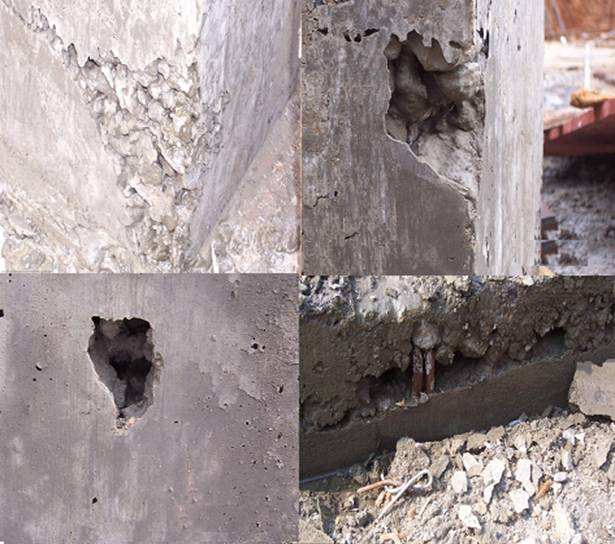
Voids: Occur when dense reinforcement obstructs concrete flow or when concrete is not properly compacted in congested areas. Leaky formwork joints can lead to severe mortar loss, forming unfilled cavities.
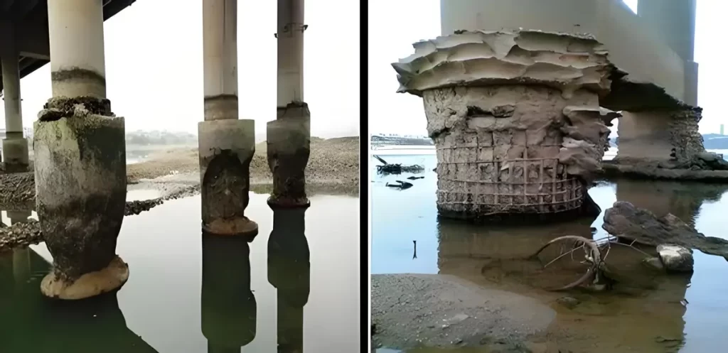
Wear and Spalling: Inadequate concrete mix design (low strength, high fine aggregate ratio, or insufficient cement paste) lowers surface abrasion resistance. Long-term vehicle wear, sand-laden water erosion, and freeze-thaw cycles cause the surface layer to degrade and delaminate.
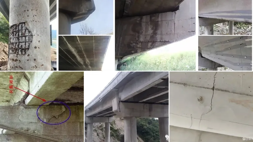
(2) Structural Crack Damages
Cracks are the primary form of structural deterioration that threatens bridge safety. They have complex causes and tend to develop progressively. Major types include:
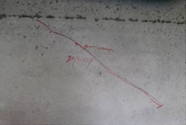
Map Cracks: These typically occur due to improper curing after concrete pouring. When surface moisture evaporates rapidly under wind or temperature fluctuations while internal moisture dissipates slowly, a large difference in shrinkage rate arises between the surface and the interior. This creates non-uniform shrinkage stress, and once it exceeds the early tensile strength of the concrete, irregular, interlaced fine cracks appear on the beam surface. The crack width is usually 0.03–0.05 mm. Although the initial damage is minor, these cracks significantly increase the permeability of water and corrosive substances, accelerating internal reinforcement corrosion.
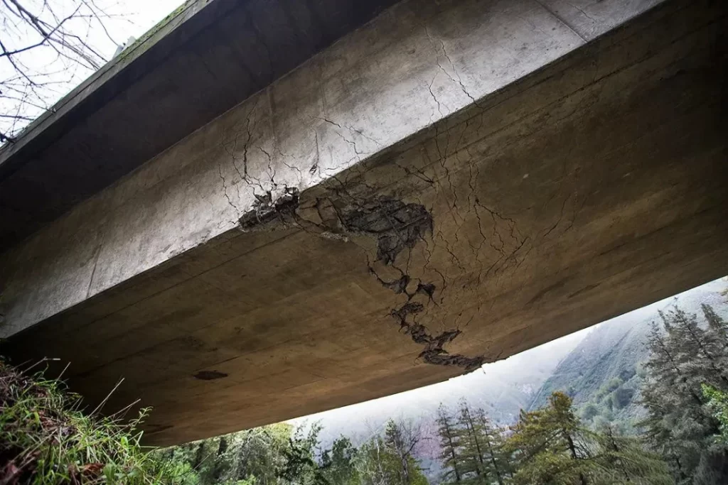
Cracks in the Bottom Tension Zone: These cracks mainly appear near the midspan, where the bending moment is greatest. Under long-term loading, the bottom of the beam remains under continuous tension. During concrete setting, volumetric shrinkage occurs but is constrained by the beam ends, further intensifying tensile stress at the bottom. As a result, longitudinal cracks parallel to the beam axis form in the midspan region. The longer the span, the greater the bending moment and the denser the cracks. They usually extend upward from the bottom flange, spaced about 0.1–0.2 m apart, with a width of 0.03–0.1 mm. Without timely repair, repeated loads will cause the cracks to propagate, weakening the beam’s load-bearing capacity.
Vertical Web Cracks: These cracks are closely related to design, construction quality, and environmental conditions. For bridges with spans over 12 m, the web is often thin, making it prone to local stress concentration under vertical loads. The highest stress typically occurs near the mid-height of the web, where cracks 0.15–0.3 mm wide may develop. In bridges with spans shorter than 10 m, the thicker web results in finer cracks (less than 0.1 mm), often extending upward from the web rib base. Insufficient web reinforcement, poor compaction during concrete placement, or long-term exposure to moisture and freeze–thaw cycles can all accelerate the formation and development of these cracks.
Diagonal Web Cracks: These occur most frequently in the regions adjacent to the midspan, where the beam is simultaneously subjected to bending and shear forces, generating diagonal principal tensile stress. If the design underestimates this stress and fails to provide adequate diagonal reinforcement—or if the reinforcement is misplaced—diagonal cracks may form. The farther from the midspan, the greater the shear proportion and the steeper the crack angle, typically between 15° and 45°. The first cracks usually appear 0.5–1.0 m from the support, where shear force peaks, with widths below 0.3 mm. Improper mix proportions reducing tensile strength, or delayed curing that slows early strength gain, can further promote crack formation.
Horizontal Cracks on Beam Sides: These are usually caused by layered concrete pouring with excessively long intervals between layers—beyond the concrete’s initial setting time. As a result, the lower layer has already gained strength before the upper layer is placed, preventing proper bonding and reducing interlayer adhesion. When the beam later experiences deformation or shrinkage stress due to temperature changes, the two layers may separate along the interface, forming horizontal cracks parallel to the pouring plane. Such cracks typically appear around the mid-height of beam sides. If they penetrate through the section, the beam’s overall structural integrity can be severely compromised, potentially leading to delamination failure.
Longitudinal Cracks at Beam Bottom: These usually result from insufficient concrete cover thickness or improper material selection. Sparse or misaligned cover spacers can reduce the actual cover thickness, decreasing the distance between steel reinforcement and the external environment, making the steel more vulnerable to corrosion from moisture and chloride attack. Moreover, the excessive use of chloride-based accelerators to speed construction can damage the concrete microstructure, lower density and crack resistance, and accelerate corrosion. As corroded reinforcement expands in volume, it exerts radial pressure on the surrounding concrete. Once this pressure exceeds the concrete’s tensile strength, longitudinal cracks appear along the reinforcement direction. These cracks tend to extend along the beam length, and in severe cases, large areas of the bottom cover may spall off.
II. Targeted Repair and Maintenance Methods (1) Surface Defect Repair Techniques
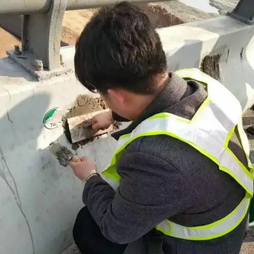
Honeycombs, Bug Holes, and Cavities: Before repair, the defective area should be properly pretreated. Use a handheld grinder or chisel to remove all loose or deteriorated concrete until a sound substrate is exposed. The surface should then be leveled and cleaned with a high-pressure water jet to remove dust and debris, ensuring a dry and clean base.
For small honeycombs and bug holes (area < 0.1 m², depth < 50 mm), use a cement mortar one grade higher than the original concrete (e.g., C40 mortar for C30 concrete). Apply the mortar in 20–30 mm layers, compacting and smoothing each layer.
For large honeycombs or cavities (area > 0.1 m², depth > 50 mm), use high-grade fine aggregate concrete (e.g., C45 concrete, maximum aggregate size ≤ 20 mm). If the void exceeds 100 mm in depth, drill injection holes at the sides and perform pressure grouting (0.2–0.4 MPa) while vibrating to prevent secondary voids. After injection, cover with geotextile and keep moist for at least 7 days to ensure proper bonding and structural integrity restoration.
Exposed Reinforcement and Spalled Cover Repair: First, identify and mark the defective area, then use an air hammer or electric drill to remove all loose or delaminated concrete until intact, rust-free reinforcement is exposed. Avoid damaging the steel bars during chipping.
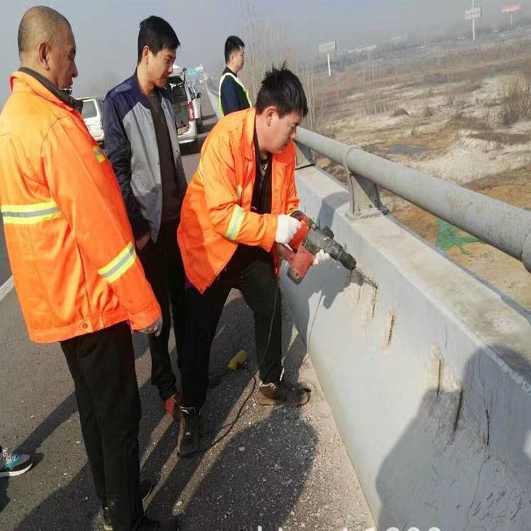
Next, remove rust using a wire brush followed by sandblasting or chemical rust removers (e.g., oxalic acid). After rinsing with clean water and drying, apply an epoxy-based anti-corrosion primer to the reinforcement.
For small-scale damage (area < 0.05 m²), use epoxy mortar (mix ratio epoxy resin: hardener: quartz sand = 1:0.2:3). Apply in layers ≤ 15 mm thick, compacting each layer for tight adhesion to both reinforcement and substrate.
For large-scale damage (area > 0.05 m²), use sprayed high-strength cement mortar (≥C40, sand ratio 35–40%). Set spraying pressure to 0.3–0.5 MPa, maintain a distance of 0.8–1.2 m, and apply in 2–3 passes to the design cover thickness. Cure each layer for 24 hours and the final layer under plastic film for at least 14 days. The finished protective layer must meet the design thickness (typically 25–35 mm for beam surfaces).
Abrasion and Surface Spalling Treatment: Cut the damaged surface into a neat rectangular shape with a diamond saw, then roughen the base (roughness depth ≥ 5 mm) using a chisel to improve bonding. Clean with compressed air and apply a bonding agent (e.g., epoxy primer, 0.5–1 mm thick). After the primer is tack-free (30–60 minutes), start repair.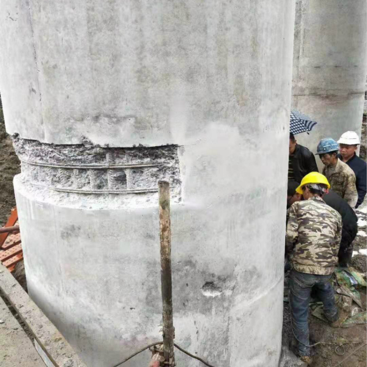
For general abrasion (without chemical or freeze–thaw damage), use high-strength repair mortar (compressive strength ≥ 50 MPa, flexural strength ≥ 8 MPa), applied to a 10–20 mm thickness and compacted before finishing.
For chemically or frost-damaged areas, use specialized materials such as sulfate-resistant mortar (for sulfate attack) or air-entrained frost-resistant concrete (air content 4–6%, impermeability ≥ P8).
After repair, cure according to environmental conditions: under normal temperature, cover with geotextile and keep moist; under low temperature (<5°C), insulate with materials like rock wool blankets. Curing should last at least 10 days to prevent cracking or delamination.
(2) Crack Repair Methods
Severe Cracks (width ≥ 0.15 mm or exceeding design limits): Clean the crack with a wire brush and compressed air, removing rust and dust. If moisture is present, use vacuum drying to ensure the crack is completely dry. Inject low-viscosity epoxy resin (viscosity ≤ 500 mPa·s, solids ≥ 95%) under low pressure (0.2–0.4 MPa) at a slow rate (≤ 0.5 L/min), starting from the lower or one end of the crack. When epoxy flows out from the opposite port without bubbles, seal and maintain pressure for 30 minutes to ensure full penetration.
After injection, coat the crack surface with epoxy resin for sealing. Allow to cure undisturbed for at least 7 days at ambient temperature. Perform ultrasonic or core sampling tests after curing to verify injection effectiveness. The repaired section must restore integrity and water tightness (impermeability ≥ P6).
Progressive or Widening Cracks: When cracks continue to widen, lengthen, or are accompanied by deformation or large-scale cover spalling, perform detailed investigation using crack gauges, load testing, concrete strength tests, and reinforcement corrosion assessments to determine the cause.
If caused by overload (e.g., heavy traffic), immediately install load restriction signs (typically ≤ 80% of design load) and limit heavy vehicles. Reinforce the structure using:
– Carbon Fiber Sheets: Use Type I carbon fiber fabric (tensile strength ≥ 3400 MPa, modulus ≥ 2.1×10⁵ MPa). Grind and clean the surface, apply primer, cut the fabric to design size, and bond it using epoxy resin, pressing to remove air. Allow 7 days for curing.
– Steel Plate Jackets: Use Q355 steel plates (6–10 mm thick) fixed with chemical anchors. Apply structural adhesive between steel and concrete to ensure full bonding.
If caused by environmental factors (e.g., humidity, chloride exposure), apply protective coatings such as polyurea corrosion-resistant layers (dry film thickness ≥ 2 mm, salt spray resistance ≥ 1000 h). Establish quarterly monitoring to track crack progression using width gauges.
Minor Cracks (width < 0.15 mm with no progression for ≥3 months): Lightly sand the surface to remove dust and oil, then wipe with acetone to ensure a clean, dry surface.
For short cracks (<2 m, no branching), apply surface sealing using epoxy resin (solids ≥ 90%, drying time ≤ 24 h). Apply in two coats, extending 50 mm beyond each side of the crack and to a total thickness of 0.5–1 mm. The second coat is applied after 4–6 hours.
For long or branched cracks (≥2 m), apply modified bitumen waterproof membranes (thickness ≥ 3 mm, heat resistance ≥ 80°C). Prime the surface first, allow to dry, then apply the membrane with a hot air gun, ensuring overlap ≥ 100 mm.
After repair, mark the area for routine inspection and monitor every six months to detect any reactivation. This prevents water and corrosive agents from penetrating and mitigates reinforcement corrosion and concrete degradation.
III. Preventive and Long-Term Maintenance
- Regular Inspection:
- Critical bridges (main routes, >20 years old, or in harsh environments): weekly inspections.
- Ordinary bridges: biweekly.
- Minor pedestrian or rural bridges: monthly.
Quantitative inspections (e.g., crack width, corrosion rate) are performed quarterly or annually, with findings entered into a digital maintenance archive.
- Environmental Protection:
Apply anti-freeze coatings in cold regions, corrosion-resistant coatings near industrial or saline environments, and maintain drainage systems in rainy climates. - Load Control:
Enforce design load limits with visible signage and weight monitoring. Increase inspection frequency on heavy-traffic or overloaded routes.
- Preventive Design and Quality Assurance
Bridge deterioration control should follow the principle of “prevention first, combined with targeted treatment.”
- Optimized Design: Select materials and reinforcement rationally based on geological and traffic conditions.
- Strict Construction Control: Ensure accurate mixing, vibration, and curing, and maintain required cover thickness.
- Systematic Maintenance: Build a long-term bridge health record and perform personalized maintenance based on defect type and progression.
Through rigorous quality control in design, construction, and maintenance, the occurrence of structural defects in reinforced concrete simply supported bridges can be significantly reduced, extending their service life and ensuring the safety and stability of transportation networks.