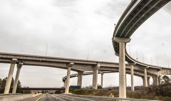
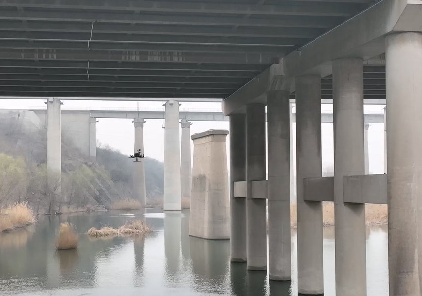
Pile-column bridge piers are widely used in highway bridges, river crossings, and elevated urban infrastructure. Their streamlined column design reduces water resistance and improves flood discharge capacity, making them particularly suitable for bridges constructed over rivers and flood-prone areas.
Among pile-column bridge components, cap beams serve as critical load-transfer elements connecting pier columns and superstructures. Because cap beams carry vertical loads from the bridge deck and distribute them to pier columns, any structural defects may directly affect overall bridge stability.
Over time, environmental exposure, traffic loading, and construction-related factors can lead to various types of cap beam and pier column defects. Identifying these issues early is essential for ensuring bridge safety and extending service life.
Why Cap Beam Inspection Is Critical in Bridge Maintenance
Cap beams function as key structural transfer components between bridge piers and superstructures. They are subjected to bending, shear forces, and temperature-induced stress throughout their service life.
Because cap beams often experience:
- Heavy traffic loading
- Temperature variation
- Long-term structural stress
- Environmental deterioration
they are vulnerable to cracking, deformation, and structural damage. If not detected early, these defects may propagate and compromise structural integrity.
Regular bridge inspection is therefore essential, particularly for aging infrastructure or bridges subjected to heavy traffic.
Vertical Cracks in Bridge Pier Cap Beams
Defect Characteristics
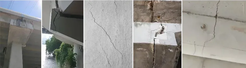
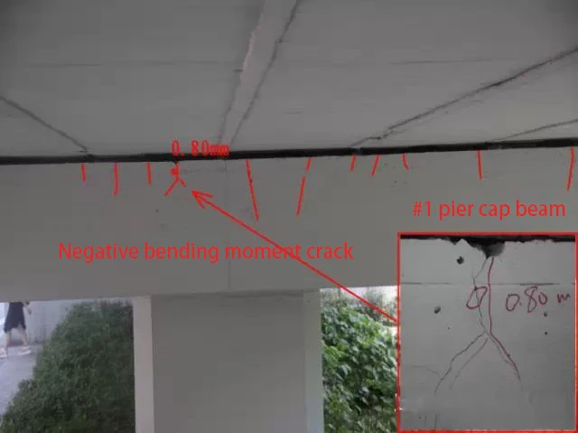
Vertical cracks are among the most common defects found in pile-column bridge cap beams. These cracks typically appear in three main patterns.
In some cases, cracks appear near the top of the cap beam and extend downward toward the neutral axis. These cracks are often wider at the top and narrower toward the bottom. Another common pattern occurs in mid-span areas, where cracks originate from the bottom edge of the cap beam and extend upward. A third type consists of longitudinal cracks distributed along the cap beam, often associated with temperature shrinkage or reinforcement corrosion.
These cracks may vary in severity, from surface-level shrinkage cracks to structural cracks that affect load-bearing capacity.
Causes of Vertical Cracks
Vertical cracks may result from construction-related shrinkage or structural design issues.
Shrinkage cracks often occur when concrete strength has not fully developed before formwork removal. Low temperatures or improper curing conditions can slow concrete strength development, leading to cracking under self-weight. High temperature and dry environments may also cause vertical cracking when curing is insufficient.
Structural cracks, on the other hand, may be caused by insufficient reinforcement design, inaccurate calculations, or excessive loading. In some older bridge designs, reinforcement layouts were based on standard drawings rather than detailed structural calculations, leading to insufficient reinforcement and increased cracking risk.
Maintenance and Repair Strategies
Repair strategies depend on crack severity and root causes. For shrinkage cracks, surface sealing or grouting methods are typically used to prevent further deterioration.
When structural cracks are identified, engineers usually reassess reinforcement design and load-bearing capacity. In cases where structural capacity needs improvement, strengthening methods such as bonded steel plates or external prestressing may be applied to restore structural performance.
Diagonal Cracks in Cap Beams
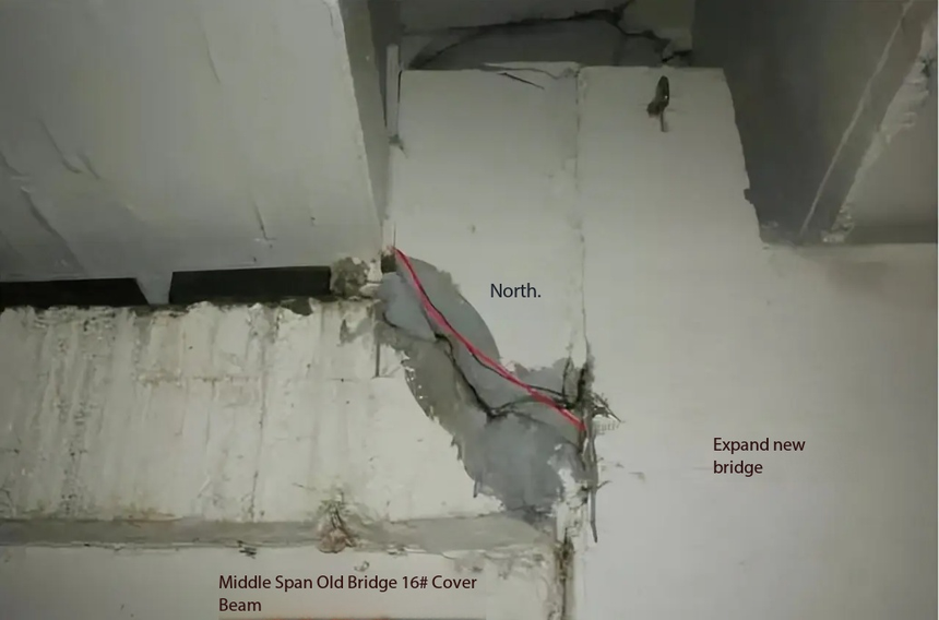
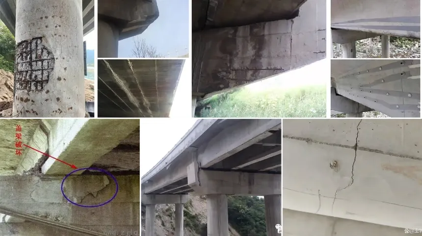
Defect Characteristics
Diagonal cracks commonly appear near pier columns and extend at an angle between 30° and 60°. These cracks often connect with vertical cracks near the top of the cap beam and are typically associated with shear stress.
Diagonal cracks are considered more critical than shrinkage cracks because they may indicate insufficient shear capacity.
Causes of Diagonal Cracks
Diagonal cracks are typically caused by insufficient shear reinforcement near pier columns. Inadequate stirrup spacing may reduce shear resistance and lead to crack development.
Another common cause is excessive loading. When traffic loads exceed design limits, shear forces may surpass structural capacity, resulting in diagonal cracking.
Repair and Strengthening Methods
When diagonal cracks are detected, engineers typically reassess structural capacity. If structural capacity remains adequate, steel plate bonding may be used to reinforce the affected area.
However, if structural capacity is insufficient and cracks are severe, increasing the cap beam cross-section may be required to restore load-bearing capacity.
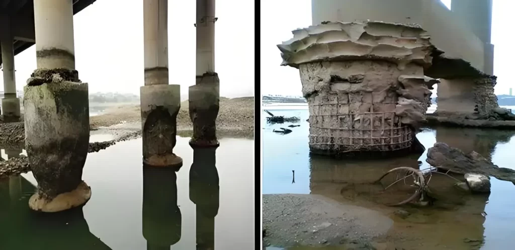
Horizontal Cracks in Pier Columns
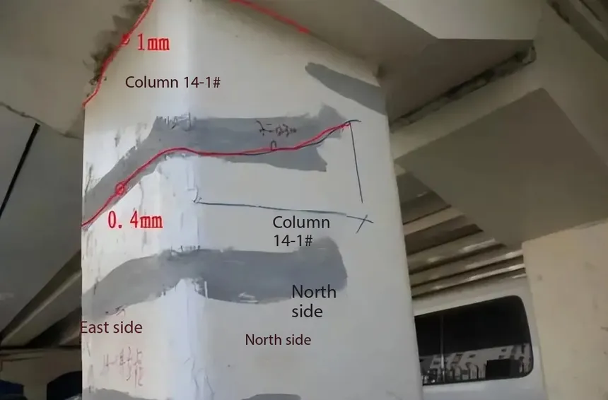
Defect Characteristics
Horizontal cracks in pier columns often appear as ring-shaped cracks around the column surface. These cracks may indicate structural stress or foundation-related issues.
Causes of Horizontal Cracks
Horizontal cracks may result from uneven settlement or horizontal pressure acting on the pier column. In some cases, soil accumulation around bridge piers may generate lateral pressure, leading to cracking.
Construction of nearby infrastructure such as underpass roads may also apply horizontal forces to bridge columns, resulting in structural damage.
Maintenance and Repair Strategies
Repair strategies typically begin by removing the source of horizontal pressure. This may involve removing soil accumulation or relieving structural constraints around bridge columns.
Once pressure is reduced, structural strengthening methods such as reinforced concrete jacketing may be used to restore column stability and improve load capacity.
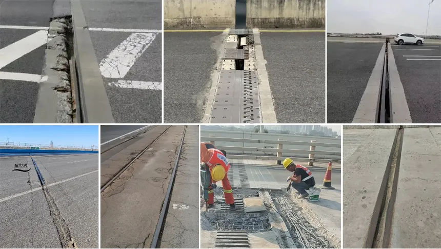
Challenges of Traditional Cap Beam Inspection
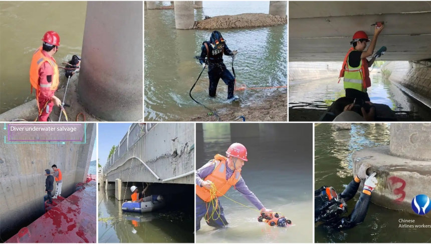
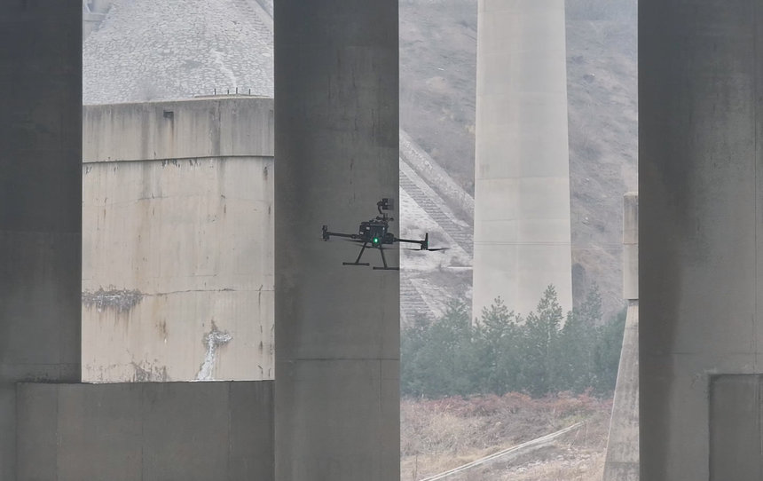
Traditional bridge inspection methods often rely on manual visual inspection and access equipment. However, cap beams located at height or above water are difficult to access safely.
Manual inspection also presents limitations in documenting small cracks or monitoring crack development over time. These challenges reduce inspection efficiency and increase safety risks.
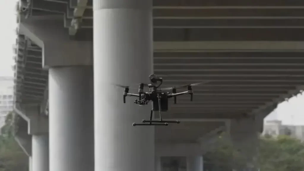
How Riebo’s Drone Bridge Inspection Solution Supports Cap Beam Inspection
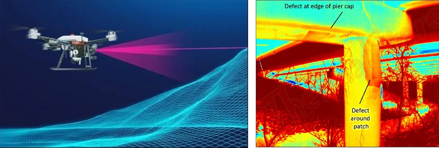
Riebo’s Drone Bridge Inspection Solution integrates drone imaging, AI-based defect detection, and digital twin modeling to support comprehensive bridge inspection.
High-resolution imagery allows engineers to identify cracks and structural defects more accurately. AI-based analysis improves detection efficiency, while digital twin models support long-term monitoring and maintenance planning.
This integrated solution enables infrastructure owners to detect structural risks earlier, reduce inspection costs, and extend bridge service life.
Conclusion
Pile-column bridge cap beams are critical structural components that require regular inspection to ensure bridge safety. Common defects such as vertical cracks, diagonal cracks, and horizontal column cracks may significantly impact structural performance.
Traditional inspection methods face limitations in safety and efficiency. Drone-based bridge inspection provides a modern solution by improving accessibility, accuracy, and data documentation.
With Riebo’s Drone Bridge Inspection Solution, bridge owners can implement proactive maintenance strategies and ensure long-term structural reliability.