Reinforced concrete slab arches, rib arches, and box arches are classified by the cross-sectional shape of the main arch ring. This discussion mainly concerns deck-type arch bridges, which vary greatly in span — from small spans of just over 10 meters to large box-rib arches exceeding 420 meters. Although structural forms differ, they tend to exhibit similar types of deterioration.
Common Structural Problems
Transverse Cracks at the Arch Crown and Abutment
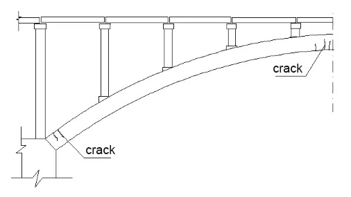
Horizontal cracks often appear along the intrados and sides near the crown, and the extrados near the arch springing. These indicate insufficient bending strength, caused by factors such as undersized sections, inadequate reinforcement, irrational arch axis design, uneven foundation settlement, excessive vehicle loads, poor construction quality, or inadequate overall integrity. If the crack positions are reversed, abutment movement toward the bridge opening is typically the cause.
Longitudinal Cracks in the Main or Spandrel Arch Rings

These cracks may also appear in the pier caps or abutment caps. If centered, they often result from differential settlement between the upstream and downstream sides of the foundation. Cracks at the joints between side arch boxes typically indicate poor joint integrity or differential deformation under eccentric loading.
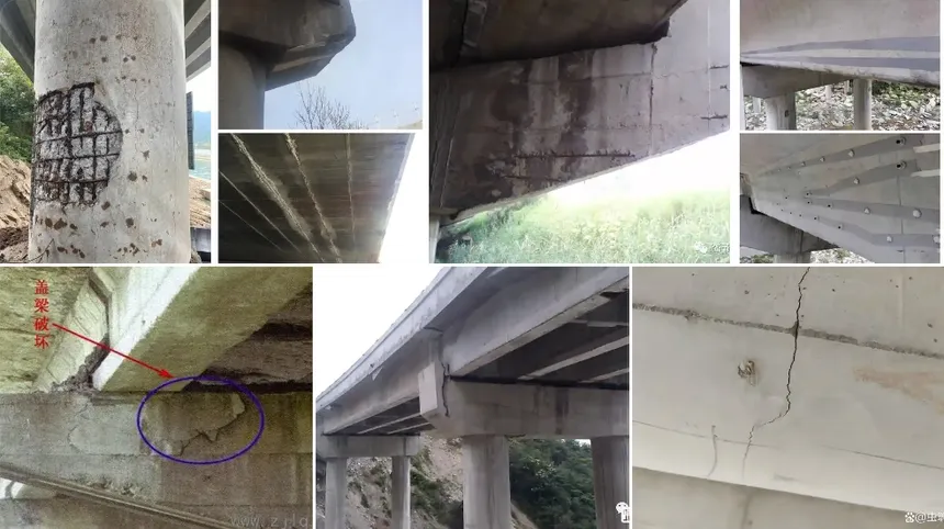
Localized Concrete Spalling or Crushing
Often observed near the arch foot or in high-compression zones, caused by insufficient compressive strength, material aging, or reinforcement corrosion and expansion.
Radial Cracks at the Arch Foot
Generally caused by insufficient shear strength of the concrete.
Longitudinal and Circumferential Cracks in Double-Curved Arches
Cracks at the arch wave crest or at rib-to-wave connections result from weak transverse links, poor structural integrity, or lateral differential settlement of the foundations.
Cracks in the Spandrel Frames, Beams, or Short Columns
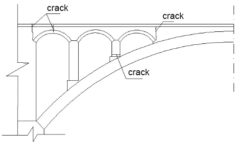
Particularly at both ends of short columns or near solid web segments. These result from the absence of hinges or expansion joints, causing stress concentration and cracking under arch deformation or pier displacement.
Longitudinal Cracks on the Deck
Often accompanied by vertical cracking of transverse diaphragms, indicating poor transverse integrity and uneven load distribution.
Cracks at Segmental Joints
When the main arch ring is precast and assembled, cracks frequently form at segment joints due to inadequate connection.
Defects in Concrete-Filled Steel Tube (CFST) Ribs
Surface wrinkles or internal voids may occur due to insufficient steel wall thickness, poor confinement, inadequate stiffeners, or improper concrete filling.
Strengthening Methods
For Transverse Cracks at the Arch Crown or Foot
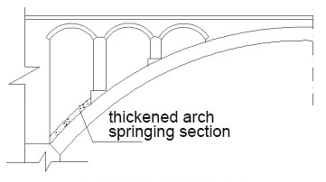
Since the main arch ring is an eccentrically compressed member, the best approach is section enlargement — roughening the surface, drilling and inserting rebar, and applying shotcrete or cast-in-place concrete.
At the arch foot, reinforcing bars should be anchored into the pier cap before enlarging the section.
Steel plate or CFRP bonding may also be used, but excessive bonding length can cause radial peeling stress.
For small- and medium-span arches, external prestressing may be applied, provided load redistribution is properly analyzed.
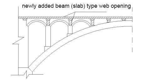
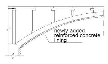
Alternatively, the self-weight of the superstructure can be reduced by replacing or removing backfill and converting solid spandrel walls into open spandrel decks.
If the damage is caused by foundation movement, the substructure should be stabilized first.
For Longitudinal Cracks in the Arch Ring or Piers

If the cracks continue to propagate, the foundations must first be reinforced. Then, depending on crack width, apply grouting, section enlargement, steel or CFRP bonding, or steel hoop confinement with closed loops or transverse prestressing rods.
For Cracks in Double-Curved Arches or Rib Connections
Enhance transverse links, enlarge rib or web sections, add more ribs, or reduce the dead load of the superstructure by modifying the spandrel type or replacing heavy fill materials.
If caused by uneven foundation settlement, strengthen the ground first.
For Cracks at Short Spandrel Columns or Near Abutments

Replace rigid joints with hinged (necked) connections to allow limited rotation.
If severe cracking or offset occurs at the arch foot or crown, partial reconstruction into a two- or three-hinged system may be necessary.
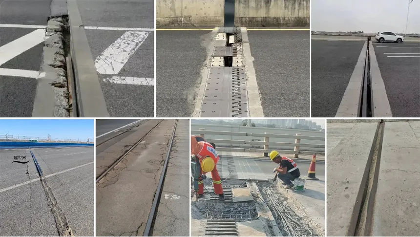
Deformation joints at sidewalls and decks must be properly designed to prevent leakage.
For Deck Longitudinal Cracks or Transverse Connection Cracks
Improve transverse stiffness by widening or adding crossbeams, increasing deck slab thickness and strength, and enhancing transverse reinforcement.
In filled arches, consider replacing fill with reinforced concrete for improved integration.
For Joint Cracks in Segmental Arches
Strengthen the connection by grouting, dowel bar anchoring, or welding reinforcement.
For Defects in CFST Ribs
Add an external reinforced concrete layer, install more diaphragms or stiffeners, or inject epoxy/cement grout into internal voids.
For Excessive Arch Deflection and Intrados Cracking

Install external prestressing tendons anchored above the elastic center of the arch to induce counter-bending moments.
The tendon layout and tension should be determined through iterative stress analysis.
Since this also introduces negative moments at the arch foot, the arch base should be strengthened accordingly.
For Severe Arch Deformation due to Abutment Movement
When other reinforcement methods are ineffective, arch foot jacking and realignment may be used to restore the original thrust line. However, this method is technically complex, costly, and risky — suitable only for critical bridges.
During Reconstruction or Section Enlargement
Ensure uniform and symmetrical loading/unloading between spans to maintain arch and pier stability.
RIEBO’s Intelligent Bridge Inspection and Reinforcement Solutions
RIEBO Tech provides a full suite of intelligent inspection and structural strengthening advices tailored for different bridges:

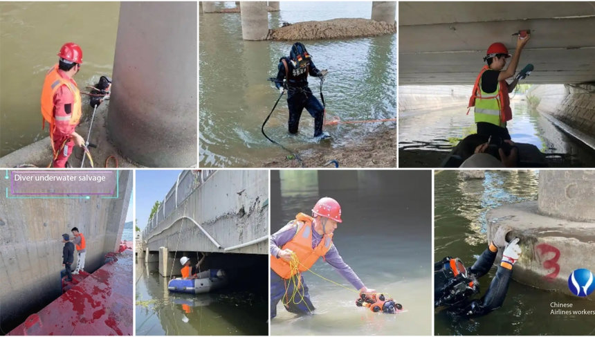
- Drone + AI Visual Inspection – High-resolution UAVs automatically identify cracks, spalling, and corrosion on the beam soffit, webs, and anchorage zones.
- Digital Twin Modeling – Converts inspection data into a 3D structural model for visualization, analysis, and defect progression prediction.
- Customized Strengthening Design – Provides detailed reinforcement plans such as CFRP strengthening, external prestressing, or beam replacement based on inspection data.
- Lifecycle Health Management – From inspection to post-reinforcement monitoring, RIEBO builds a comprehensive digital health record for each bridge, optimizing long-term maintenance and safety.
Looking to assess or strengthen your bridge structures?
Contact RIEBO today for a professional UAV inspection and customized reinforcement plan — empowering safer, longer-lasting bridges with intelligent technology.