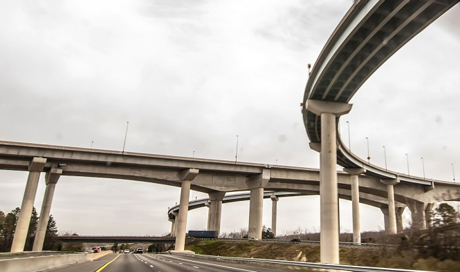
Continuous and cantilever beam bridges are widely used in highway overpasses and urban interchanges. Their typical cross-sectional shapes include T-shaped, I-shaped, and box-girder forms. For spans over 30 meters, box girders are commonly adopted, usually designed as variable-depth, unequal-span beams. Constant-depth reinforced concrete continuous beams are typically used for spans below 30 meters, while variable-depth RC continuous or cantilever beams can reach up to 50 meters. When longer spans are still built using reinforced concrete, material consumption increases significantly, and transverse cracks often develop in the negative moment regions of the deck. Constant-depth prestressed concrete continuous beams are generally used for spans up to 60 meters, while variable-depth prestressed cantilever beams can reach 100 meters or even more. Continuous prestressed beams often span up to 200 meters, though longer examples exist.
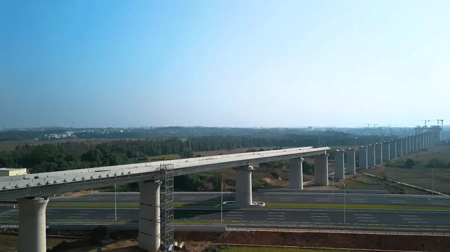
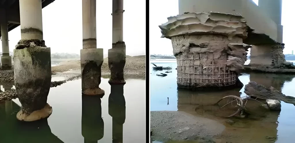
These bridge types are often employed to cross rivers, valleys, or urban roads. However, regardless of span length, they are prone to a variety of structural defects during service.
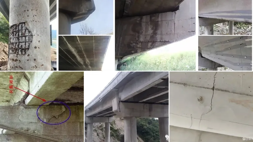
Common Structural Problems
(1) Reinforced and Prestressed Concrete Cantilever Beams
1. Excessive Deflection at Cantilever Ends
This often leads to cracking on the deck above the pier. Causes include insufficient stiffness of the cantilever, undersized dimensions, overloading from heavy vehicles, large loss of longitudinal prestress, or poor construction quality.
2. Local Cracks near the Cantilever Root
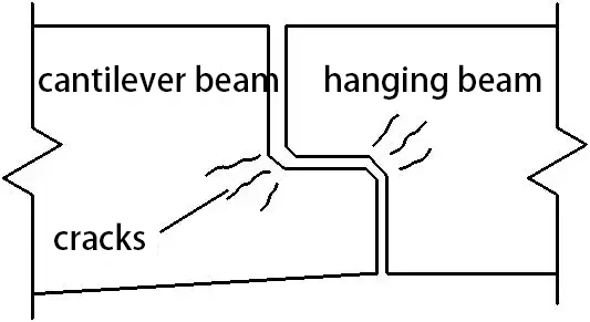
Usually caused by insufficient reinforcement, small cross-section height, temperature effects, or improper connection between the cantilever and suspended span—leading to local impact (“bump”) and cracking.
3. Midspan Deflection or Vertical Cracks at Anchorage Zones
When the anchorage span is large and reinforcement is insufficient, midspan sagging or vertical cracks may appear at the bottom of the beam.
4. Diagonal Cracks near Prestressing Anchorage Plates
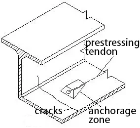
Common in prestressed box girders due to stress concentration around the anchorage block, insufficient ordinary reinforcement, or overly concentrated prestressing tendons.
5. Longitudinal Cracks on the Deck or Bottom Slab

These result from excessive transverse bending moments, insufficient transverse prestressing, thin slabs, or large internal–external temperature gradients causing thermal stress.
6. Longitudinal Cracks at the Web-Flange Junction (Haunch Zone)
Caused by concentrated prestressing tendons, insufficient shear lag consideration, or torsional stress from eccentric loads.
7. Vertical Cracks in Webs after Demolding
Usually appear within 2–3 days after casting and often close after prestressing. Causes include shrinkage, thermal differences, insufficient horizontal reinforcement, or poor concrete mix quality.
8. Diagonal Cracks in Webs (Shear Cracks)
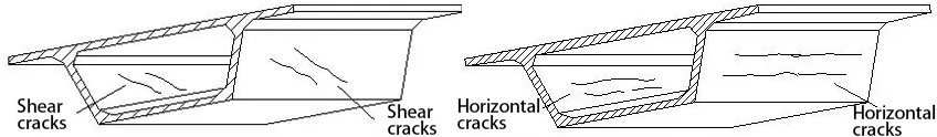
Common between supports and the point of contraflexure. They may result from insufficient longitudinal or vertical prestress, large temperature gradients, inadequate shear or torsional stiffness, poor mix quality, or improper tendon layout.
9. Horizontal Cracks in Webs
Caused by transverse bending effects and temperature stresses between inner and outer walls, insufficient vertical prestress, or poor torsional rigidity.
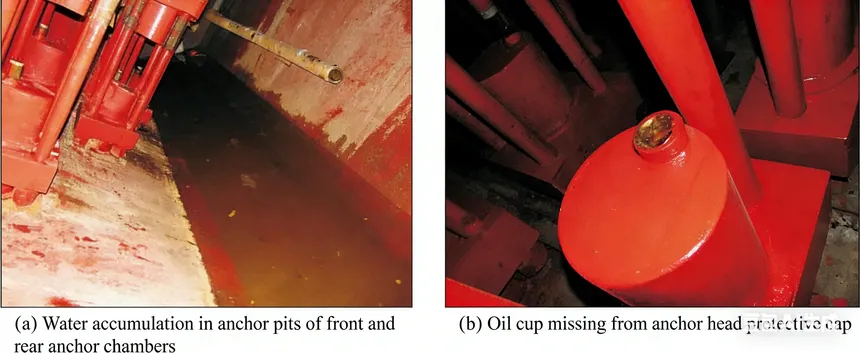
10. Cracks at Segmental or Closure Joints
Occur when construction joints are improperly treated, forming weak sections that crack under bending, shrinkage, or temperature stress. Water ingress can lead to steel corrosion.
11. Vertical Cracks in Cross Beams or Diaphragms
Often found in wide box girders due to insufficient transverse prestress, excessive prestress loss, or poor torsional resistance.
(2) Reinforced and Prestressed Concrete Continuous Beams
Excessive midspan deflection is often accompanied by transverse bottom cracks, deck cracks above piers, or diagonal cracks in webs. The main cause is insufficient flexural stiffness, such as undersized beam depth, thin webs, or loss of longitudinal prestress. Other defects are similar to those found in cantilever beams.
Strengthening and Rehabilitation Methods
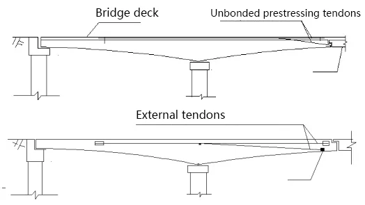
1. Supplemental Prestressing for Excessive Deflection
The most effective approach is to add new prestressing tendons. For variable-depth girders, unbonded tendons can be placed within the pavement layer and anchored at the cantilever ends. When box height allows, external prestressing tendons can be installed along both sides of the inner webs.
This enhances stiffness and restores the structure’s original alignment.
2. Crack Repair at Cantilever Roots
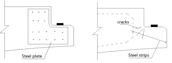
Apply steel plates or strips to both sides of the cracked region. If internal access is available, prestressing tendons can be installed through inclined holes from the outer surface and anchored after tensioning.
3. External Prestressing for Continuous and Cantilever Beams
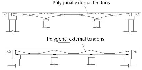
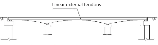
Installing linear or polygonal external tendons inside the box girders is an effective method for strengthening.
For constant-depth continuous beams, the polygonal external prestressing system is preferred to enhance both stiffness and durability.
4. Local Strengthening with Steel or CFRP Plates
For cracks near anchorage zones, inject epoxy and bond thin steel plates or CFRP composites to restore tensile capacity.
5. Pier-Top Deck Cracks
Remove deteriorated concrete from the pavement layer and add longitudinal reinforcement or unbonded prestressing tendons anchored in the overlay.
Alternatively, external tendons can be installed above the neutral axis inside the box girder.
6. Cracks in Beam Bottoms or Segment Joints
Strengthen using bonded CFRP or steel plates, or apply external prestressing.
For non-structural cracks, epoxy sealing is sufficient.
7. Longitudinal Cracks on Decks or Bottom Slabs
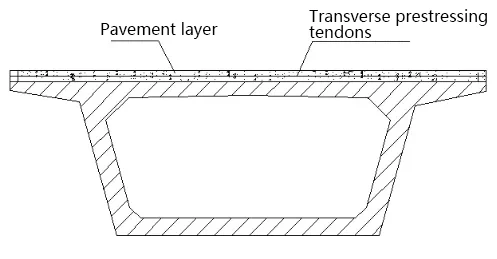
Apply transverse steel or fiber composites, or add transverse prestressing tendons in the pavement layer to improve lateral rigidity.
8. Cracks in Haunch Zones or Webs
Use crack sealing, epoxy injection, or CFRP bonding for repair.
9. Shear Cracks in Webs
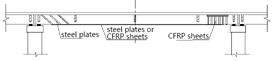
Strengthen by bonding steel plates or CFRP sheets on the web surface, adding vertical or longitudinal prestressing, or thickening the web section.
10. Horizontal Cracks in Webs
Repair by bonding vertical reinforcement plates, adding transverse diaphragms, or applying vertical prestress.
11. Cracks in Cross Beams or Diaphragms
Apply transverse external prestressing anchored through the box wall, or add additional diaphragms to enhance torsional stiffness.
RIEBO’s Intelligent Bridge Inspection Solutions
RIEBO Tech provides a full suite of intelligent inspection and structural strengthening advices tailored for different bridges:

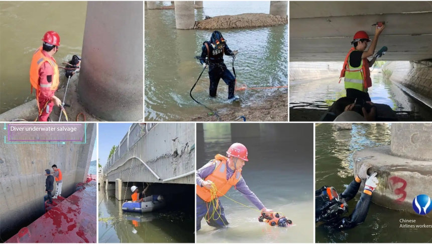
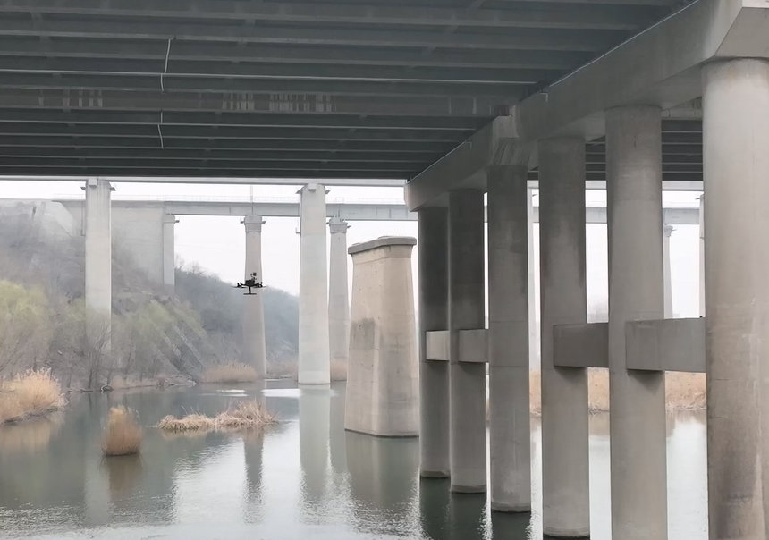
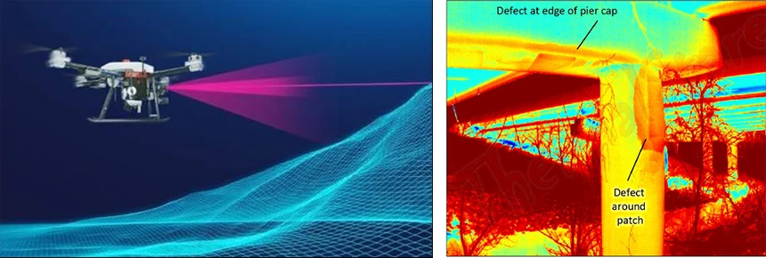
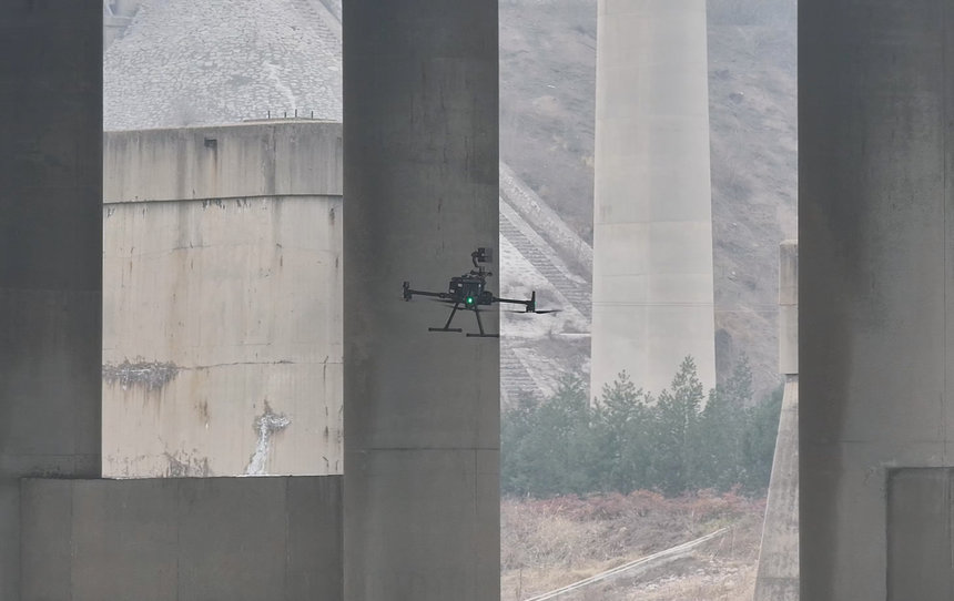
- Drone + AI Visual Inspection – High-resolution UAVs automatically identify cracks, spalling, and corrosion on the beam soffit, webs, and anchorage zones.
- Digital Twin Modeling – Converts inspection data into a 3D structural model for visualization, analysis, and defect progression prediction.
- Customized Strengthening Design – Provides detailed reinforcement plans such as CFRP strengthening, external prestressing, or beam replacement based on inspection data.
- Lifecycle Health Management – From inspection to post-reinforcement monitoring, RIEBO builds a comprehensive digital health record for each bridge, optimizing long-term maintenance and safety.
RIEBO’s intelligent system provides a complete life-cycle bridge management solution, improving structural reliability, reducing maintenance costs, and extending service life.
Conclusion
Continuous and cantilever beam bridges, whether reinforced or prestressed, often face complex structural issues under long-term service conditions.
However, through precise diagnosis, advanced materials, and intelligent rehabilitation techniques—such as external prestressing and CFRP strengthening—these structures can be effectively restored to safe, durable operation.
RIEBO combines UAV inspection, AI defect detection, and smart strengthening design to deliver innovative, efficient, and sustainable solutions for modern bridge engineering.