Overview of Post-Tensioned Prestressed Concrete
In bridge construction, post-tensioning technology is widely used for its outstanding performance. However, since bridge projects require strict quality control, construction quality must be meticulously managed when applying post-tensioned prestressed concrete.

Post-tensioned concrete refers to a technique where localized compressive stress is applied to key load-bearing parts of a concrete member. In bridge projects, high-strength steel bars and strands are used to maintain a prestressed state. These materials share part of the external load during service, enhancing load-bearing capacity and crack resistance, thereby improving bridge durability and performance.
When bridges experience excessive stress during operation, cracks may occur. Post-tensioning technology effectively pre-stresses the reinforcement, redistributing loads, and reducing the risk of cracking and deformation. Thus, its promotion and application are crucial, as this technique plays a significant role in improving the structural safety and service life of bridges.
Analysis of Crack Causes
2.1 Project Overview
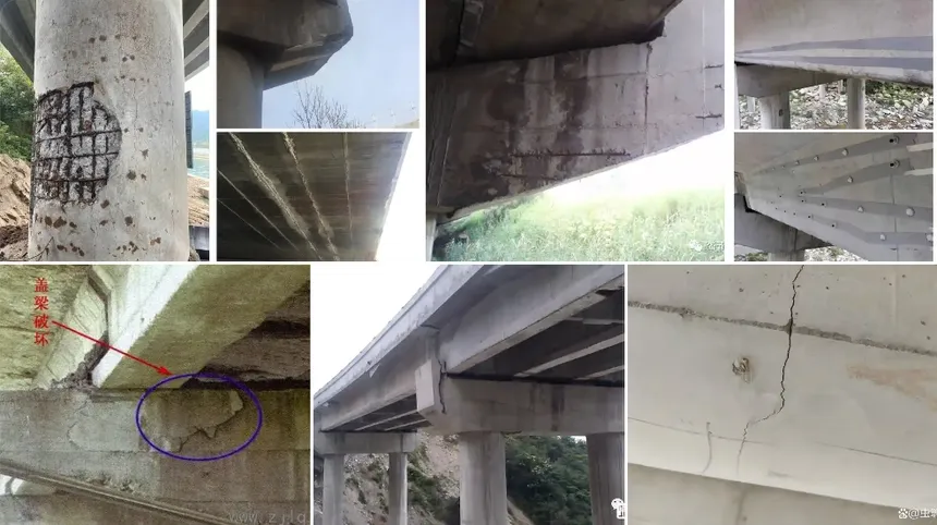
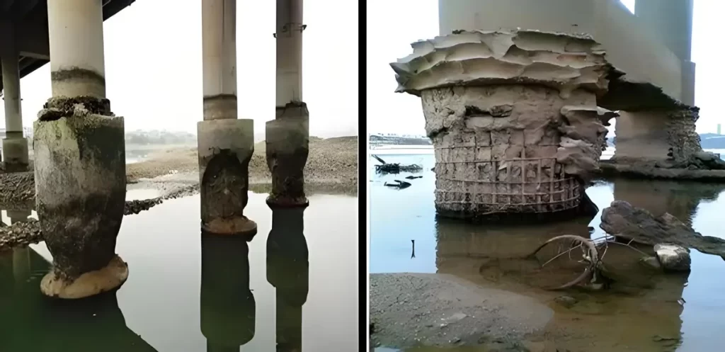
The project involves a 60-meter prestressed concrete tied-arch bridge. The tie beam, made of C50 concrete, features a solid rectangular cross-section measuring 1.2 meters in width and 2.4 meters in height. The anchorage system adopts YM15-8 anchors with 15.2-millimeter low-relaxation, high-strength steel strands (fpk = 1860 MPa). Once the concrete achieved its full design strength and exceeded ten days of curing, tendons N1 and N6 were symmetrically tensioned and grouted. During the construction process, cracking was observed—first at the southwest arch footing during the tensioning of tendon N6 under maximum load, and later at the northwest and northeast arch footings following the completion of tendon N1 tensioning.
2.2 Cause Analysis
Cracks at the tensioning ends of post-tensioned beams are typically caused by:
Poor concrete quality or insufficient vibration, leading to cracking during tensioning.
Incorrect reinforcement layout — failure to install spiral reinforcement and anchorage meshes as designed, causing perpendicular stress cracks.
Shrinkage-induced microcracks in concrete.
Incorrect tensioning force, not matching the design value.
Improper handling of rebar and ducts — when conflicts occurred between corrugated ducts and rebars, workers adjusted the tendon location instead of repositioning the rebar, reducing the distance between the anchor plate and concrete edge.
Improper anchorage selection — using nonstandard or undersized bearing plates, reducing local bearing capacity.
On-site inspection showed that concrete quality and rebar arrangement met specifications. The cracks were mainly caused by issues (5) and (6):
The square bearing plate specified (22×22 cm) was replaced with a circular plate (diameter 185 mm), cutting the effective bearing area nearly in half.
The anchor plate position was moved at tendon N6 to leave space for support anchor bolts, reducing the edge distance. The local bearing area Ab was only 800 cm² (20×40 cm), two-thirds of the standard 1200 cm² (30×40 cm), leading to localized overpressure and cracking.
Crack Treatment Measures
Increase local bearing area:
Add a 25×25×3 cm steel plate between the circular bearing plate and the anchor plate to expand the contact area and reduce localized stress. The concrete surface should be polished flat, coated with steel plate adhesive, and fixed per design. Tensioning can only resume after inspection and approval.
Repair cracked arch footings:
- Release tension and remove cracked concrete around N6 tendons without damaging the central strands.
- Reinstall spiral reinforcement and the anchorage rebar mesh.
- Replace removed concrete with epoxy-modified cement mortar to enhance bonding and local bearing capacity.
- Mix epoxy resin on-site according to the specified ratio and ensure proper curing before proceeding.
Improve anchorage bond strength:
Use JC-K20 high-performance grouting material for tendon ducts to enhance bond strength and reduce anchor load.
Its compressive strength reaches over 30 MPa at 3 days, 50 MPa at 7 days, and 60 MPa at 28 days, offering excellent fluidity and minimal loss.
Preventive Measures
Strict material inspection:
Use only qualified prestressing materials. Check certificates, factory reports, and conduct random supervision testing.
Required tests include:
- Tensile strength of strands
- Anchorage hardness and static load performance
- Spiral duct compression and permeability resistance
- Cement physical properties
Unqualified materials must be strictly prohibited on-site.
Ensure concrete strength before tensioning:
Tensioning should begin only when the concrete reaches the design strength.
- Follow symmetrical tensioning where specified.
- Conduct detailed technical briefings before operation.
- Quality inspectors and supervisors must be present throughout the tensioning process.
- Control three key factors: stress, elongation, and holding time, ensuring symmetrical elongation on both ends.
Proper reinforcement detailing:
- Accurately position spiral reinforcement and anchorage meshes (minimum four layers).
- For tendons near edges, use additional right-angle hooks for better anchorage.
- Provide dense stirrups in anchorage zones.
Adhere strictly to design drawings:
- Avoid relocating ducts; adjust rebar instead if conflicts occur.
- Designers should specify bearing plate dimensions along with anchorage types and recommend square plates to ensure sufficient bearing area.
Conclusion
Anchor zone stress behavior is a complex topic.
This article analyzes it from the perspective of bearing plate size and construction practices. The tensioning process in prestressed concrete bridges is critical, directly affecting structural quality and service life.
Therefore, it is essential to strictly control tensioning-induced cracking, paying close attention to every stage — from design and material selection to construction and supervision — to ensure the long-term safety and durability of prestressed concrete bridges.