During a bridge’s service life, various loads — including vehicle impact, vibration, self-weight, and environmental effects — generate different stress conditions. When these stresses exceed the material’s capacity, load-induced cracks occur. These cracks are among the most common and representative structural issues in bridges, significantly affecting their durability and safety.
I. Main Locations of Load-Induced Cracks
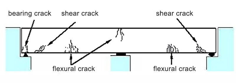
Load-induced cracks typically appear in areas with stress concentration, where repeated loads and fatigue effects make cracking more likely. They are mainly found in:
Tensile zones (e.g., beam bottoms and webs under tension), where cracks are most concentrated;
Shear zones (near supports or beam–pier connections), where diagonal cracks are common;
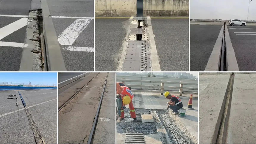
High-vibration areas (such as mid-span regions or joints with frequent vehicle impact).
II. Mechanism of Crack Formation
Under static and dynamic loads, as well as secondary stresses, two main types of cracks develop:
Direct stress cracks — caused when external loads generate stresses exceeding the tensile or shear strength of concrete.
Secondary stress cracks — formed when deformation or restraint-induced secondary stresses appear under loading.
Both types often occur in tensile, shear, or high-vibration regions.
III. Examples of Cracks Caused by Different Load Types
1. Construction Load Cracks
When external loads are applied before concrete reaches sufficient strength — such as early formwork removal, material stacking, or unstable supports — cracks often appear near beam bottoms or supports. These are usually irregular and result from improper early-age loading.

2. Long-Term Load Cracks
Continuous loads (including self-weight and sustained traffic loads) can cause creep and shrinkage. If design safety margins are insufficient or reinforcement is inadequate, tensile zones may develop longitudinal cracks that widen over time.
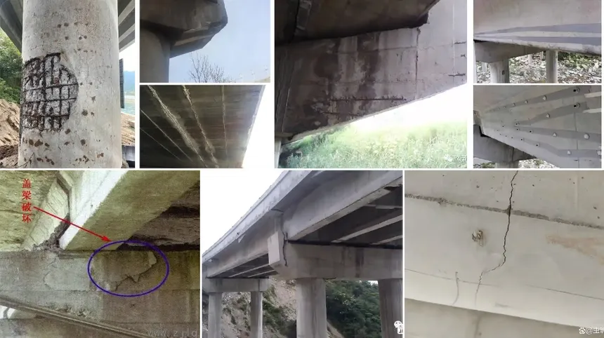
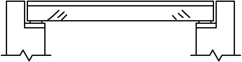
3. Shear Cracks
When beam loads are excessive, or concrete strength and shear reinforcement are insufficient, V-shaped or diagonal shear cracks form near beam ends or supports. If not controlled, these can severely weaken structural integrity.

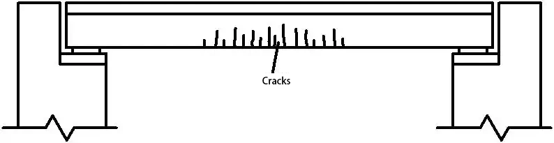
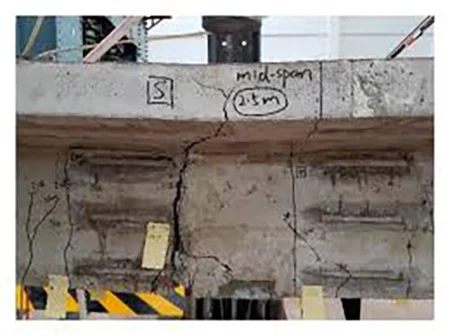
4. Deflection-Induced Cracks
Improper deflection control or insufficient top reinforcement in flexural zones can lead to cracks exceeding 1 mm in width on the top surface of beams or slabs, typically spreading along the mid-span as bending moments redistribute.
5. Fatigue Load Cracks
Even when load levels are below theoretical cracking thresholds, repeated vehicle loading can cause fatigue-induced cracks in concrete. Initially fine and located near the tensile zone bottom, these cracks expand and multiply over time, reducing bond strength and overall structural performance.
IV. Hazards of Load-Induced Cracks
Load-induced cracks can:
- Reduce the integrity and load-bearing capacity of concrete;
- Weaken crack resistance and stiffness;
- Create paths for water and chloride ingress, accelerating steel corrosion;
- Increase deformation and vibration;
- In steel bridges, lead to fatigue cracking and sudden failure.
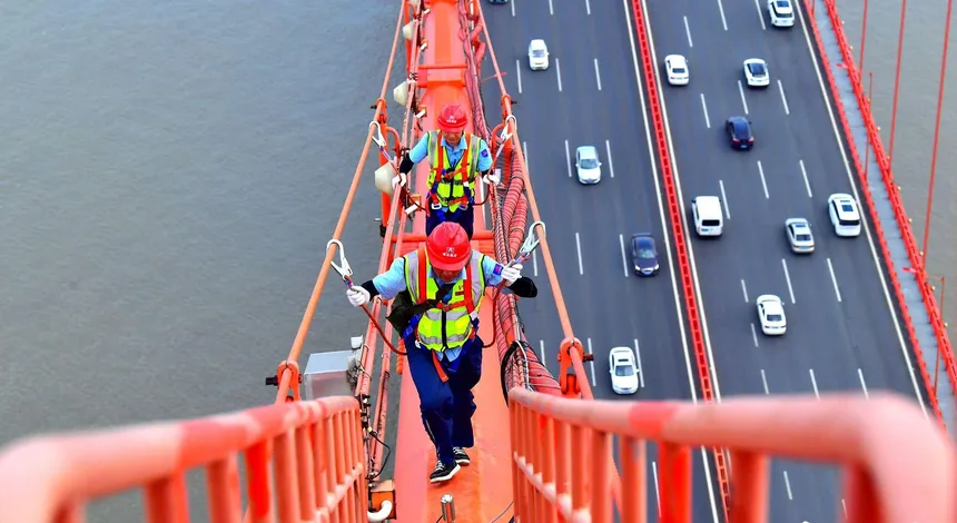
Therefore, early detection, monitoring, and evaluation of load-induced cracks are critical for bridge maintenance and safety management.
Riebo’s UAV Bridge Inspection Solution
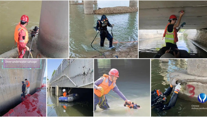
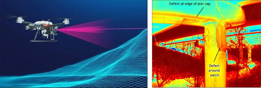
To address challenges such as difficulty in manual inspections, high risk, and insufficient accuracy, Riebo Technology has developed an intelligent bridge inspection system integrating UAVs, digital twins, and AI recognition, significantly improving the efficiency and precision of crack detection.

1. Digital Twin Modeling
High-resolution aerial imagery captured by drones is used to generate 3D reality models of bridges, providing a precise foundation for crack identification and location mapping.
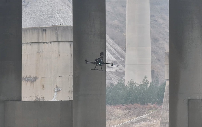
2. Automated Flight Path Planning
Based on the 3D model, the system automatically plans inspection routes covering decks, webs, piers, and bearings, ensuring comprehensive and blind-spot-free imaging.
3. Intelligent Crack Recognition
AI algorithms perform pixel-level crack detection, identifying various load-induced crack types — including tensile, shear, and fatigue cracks — and automatically outputting parameters such as crack width, length, and orientation.
4. Change Trend Monitoring
Inspection data from different periods can be compared to analyze crack propagation trends, helping assess deterioration caused by long-term or fatigue loading.
5. Intelligent Reporting and Decision Support
The system automatically generates visual analysis reports, linking with maintenance databases to provide repair priority recommendations for decision-makers.
V. Conclusion
Load-induced cracks are among the most common and dangerous forms of bridge damage, closely linked to external loading, design quality, construction conditions, and long-term service.
With Riebo’s UAV bridge inspection solution, managers can accurately detect and monitor crack development without bridge closures or high-risk manual work, significantly enhancing inspection efficiency and safety — providing strong technical support for intelligent bridge maintenance and management.