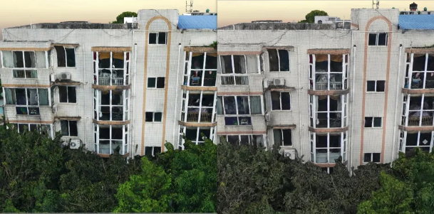
In oblique aerial photogrammetry, surveyors employ various measures to improve model accuracy. Among these, the layout of ground control points (GCPs) is one of the most fundamental methods. The selection of GCP locations and the accuracy of their coordinates directly affect the geometric precision of the final photogrammetric model. This article introduces key considerations for GCP layout under different survey area conditions, aiming to provide practical guidance for improving mapping accuracy.
I. Basic Principles of GCP Layout
1. Selection of GCPs
- GCPs should be evenly and spatially distributed across the survey area.
- Points at the same location should be measured as both planimetric and elevation control points.
- The distribution of GCPs should avoid forming near-straight lines.
- GCPs should be placed near the centerline of the side overlap. If the offset from the flight line exceeds 3 cm, additional points should be established.
2. GCP Layout Methods
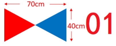
- Use different-sized targets depending on the required accuracy. For example, in land survey projects, 40cm × 35cm triangular targets are recommended, preferably with blue and red triangles sprayed on the ground for visibility. If unavailable, a solid red target may be used. The point ID should be marked nearby.
- If triangular targets cannot be used, a red cross with a concentric blue circle (size based on image resolution) can be applied.

- Avoid placing GCPs in obstructed locations such as under trees, eaves, steep slopes, or roof edges. Select relatively flat, open surfaces whenever possible.
- GCPs should be measured with RTK GNSS.
- GCP spacing should be 100–150 m.
- Each GCP should be surveyed three times, with RTK reconnection between sessions. Each observation should include 10 position averages (smoothing). Similarly, check points should be established using the same approach.
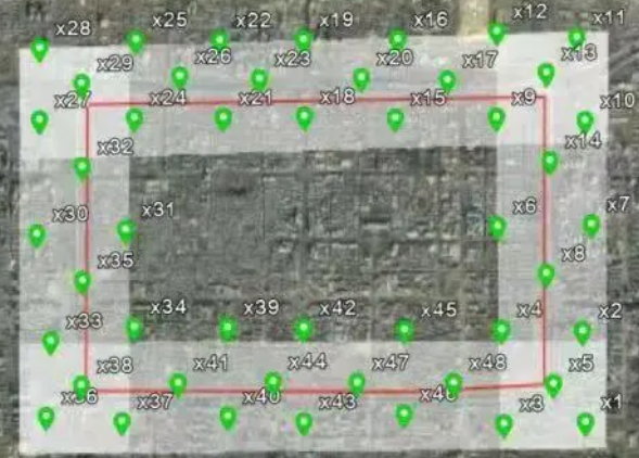
II. GCP Layout in Regularly Shaped Areas
For regular survey areas, GCP coordinates and elevations can be refined through aerial triangulation. Common layout strategies include the six-point method, eight-point method, and five-point method.
- Six-Point Method: Standard and widely used, suitable for mountainous or hilly terrain. GCPs are placed near the principal points of photo strips—at both ends and in the middle, with paired plan/elevation points distributed along overlaps.
- Eight-Point Method: Eight control points are placed per strip, allowing for higher-order polynomial corrections during block adjustment.
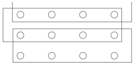
- Five-Point Method: Used for shorter strips that exceed half but are less than three-quarters of the maximum permissible length. One control point is placed near the center of the strip.
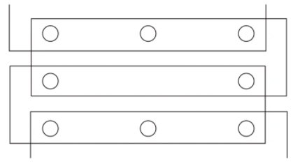
General rules:
- GCPs should be reusable across 5–6 overlapping photos.
- The distance from the image edge should exceed 150 pixels.
- The distance from any fiducial marks on the image should be greater than 1 mm.
- GCPs should ideally lie near the centerline of the side overlap. If the overlap is too small, separate points must be placed, ensuring the vertical split distance is less than 2 cm.
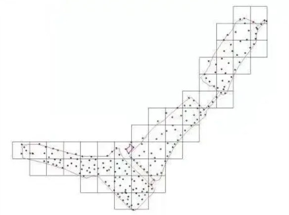
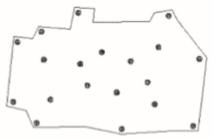
III. GCP Layout in Irregular Survey Areas
For irregular areas, GCPs should ideally be distributed so that their connecting lines cover the entire survey region. Internal points should be added as needed to reflect terrain features and improve accuracy.
- Irregular Areas: Place sufficient control points around the periphery of the survey area to enclose the region. Add a few strategically placed internal points to ensure accuracy while minimizing cost and workload.
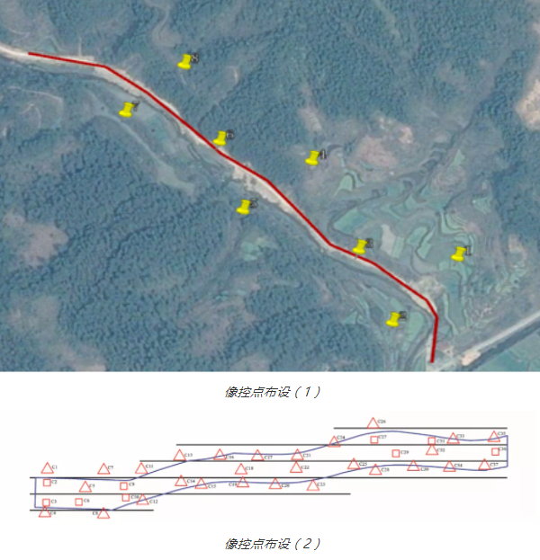
- Strip-Shaped Areas: Typically arranged in pairs perpendicular to the strip’s edges, plus one point in the center. For areas lacking distinct ground features (e.g., deserts, farmland), cloth markers may be preferable to paint.
IV. Point Identification, Annotation, and Surveying
Point Marking: The deviation of marked control points on aerial photos must not exceed 0.1 mm. Elevation points on distinctive features (e.g., peaks, saddles) should be identified with stereoscopic observation for accuracy.
Annotation: Each GCP must be assigned a unique ID. At least three photos should be taken: one close-up of the marker, and two wider shots showing surrounding reference features.
Surveying:
- GCPs can be measured using CORS RTK; in weak signal areas, static GPS mode should be used.
- Horizontal and vertical accuracy must not exceed ±0.02 m.
- Each GCP should be observed three times, with at least 60 seconds between sessions. Averaged results are adjusted to yield the final 3D coordinates.
V. Additional Measures to Improve Accuracy
Beyond GCP placement, accuracy can also be improved by optimizing equipment and workflows:
- Using cameras with well-matched focal lengths.
- Enhancing optical components to reduce image distortion.
- Improving camera synchronization to minimize timing errors.
- Applying specialized processing software to reduce cumulative aerial triangulation errors.
- Deploying UAVs with higher-grade positioning and flight stability systems.