Project Snapshot
| Item | Details |
| Project | Stay Cable and Pylon Periodic Inspection |
| Location | Shandong Province, China |
| Bridge Type | Cable-stayed highway bridge with steel–concrete composite continuous beam |
| Inspection Scope | Pylons (shaft, top, crossbeams), stay cables (body, HDPE sheath), cable-deck anchorage zones |
| Inspection Method | UAV photogrammetry + LiDAR + AI-assisted defect detection + 3D digital twin |
| Key Technologies | Autonomous flight route planning, LiDAR rapid cable focusing, RIEBO AI defect recognition, 3D defect localization, RIEBO inspection management platform |
| Project Period | April 2026 (1 field day) |
Project Overview
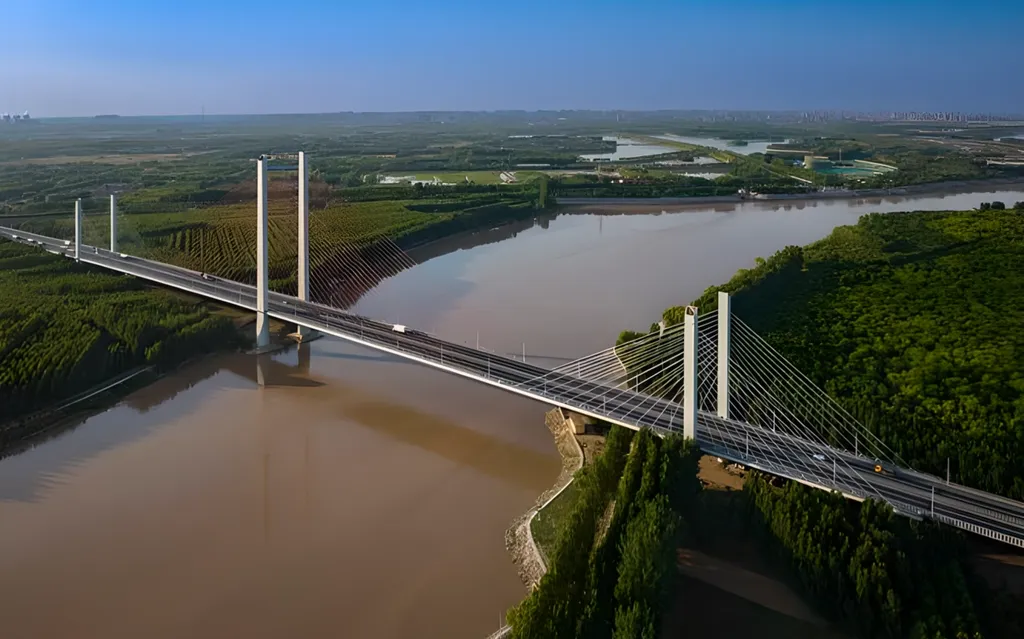
The Binzhou Yellow River Highway Bridge is a cable-stayed highway bridge spanning the Yellow River in Shandong Province, China. The main bridge is 768 m long, with a total bridge length of 1,698.4 m and a deck width of 32.8 m. Its main span arrangement is (80 + 5 × 190 + 80) m on a steel–concrete composite continuous beam. The central pylon stands 125.25 m tall, while the north and south side pylons reach 76.778 m, with the full fan of stay cables fanning out across the river.
The inspection focused on the pylons (shaft, pylon top and crossbeams) and the stay cables (cable body and HDPE sheath), together with the cable-deck anchorage zones. The primary objective was to collect high-definition imagery of these high-risk, hard-to-reach areas for a routine periodic inspection, so that surface defects such as corrosion, cracks and sheath damage could be screened at low cost, safely and with full coverage — supporting safe continuous highway operation.
Because the structure crosses a wide, sediment-laden river and carries heavy highway traffic, the owner required a method that could reach high-altitude, waterside components without rope access, under-bridge inspection vehicles, or extended road occupation.
Inspection Challenges
Challenge 01 — Stay Cables, Towers and Anchorage Zones High Above the River
The most inspection-critical areas—stay cables, the tower bodies and tops, cross beams, cable guide pipes, the girder top and underside and the cable anchorage zones—sit tens to more than one hundred meters above the Yellow River. Conventional access by bridge inspection vehicle baskets, manned baskets and rope access is slow and exposes personnel to fall and over-water hazards, and large blind spots remain around cable crossings, guide pipes and anchor zones, where small corrosion, cracks and sheath damage cannot be resolved by telescope observation from the bank at any practical distance.
Challenge 02 — Busy Cross-River Highway: the Cost of Lane Closure and Traffic Control
The bridge carries busy urban traffic. Conventional inspection of towers and cables typically requires lane closures and traffic control on the deck, converting every inspection day into commuter delay and safety exposure. The client’s objective was routine inspection that keeps the highway running—meaning access and imaging had to be achieved without the closure-and-rigging workflow of conventional methods.
Challenge 03 — Cable Array Geometry, River Wind and the Scale of the Structure
The stay cables intersect and partially block one another, and gusts over the open river make flight and imaging conditions demanding. Combined with a 1,698.4 m total length, a 32.8 m deck width and five 190 m main spans, this means full coverage requires zoned, repeatable routes that follow each tower surface and each cable individually, rather than a single generic pass over the structure.
RIEBO’s Drone Bridge Inspection Solution
To address these requirements, RIEBO deployed its Drone Bridge Inspection Solution, combining a DJI M400 RTK UAV with an SF10 inspection camera, an onboard LiDAR unit, and RIEBO’s proprietary inspection software stack.
Autonomous Flight Route Planning for Pylons and Stay Cables
Rather than relying on manual flying, RIEBO planned three mission-specific route families in advance: pylon-orbit routes around each tower shaft, follow-the-cable routes that tracked each stay cable from anchorage to pylon, and deck-bottom routes under the main span. This repeatable, pre-planned approach is what allowed a multi-pylon, multi-cable structure to be worked through in a single field day.
LiDAR-Assisted Rapid Cable Focusing
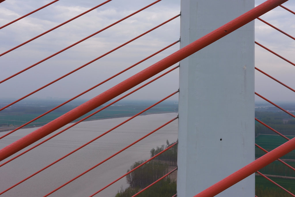
A LiDAR unit was used to rapidly lock stand-off distance and focus onto the target stay cable even when other cables sat directly behind it in the line of sight. This directly addressed the crossed-cable occlusion challenge and kept the red HDPE sheath in sharp frame across long cable runs.
AI-Assisted Defect Recognition and 3D Defect Localization
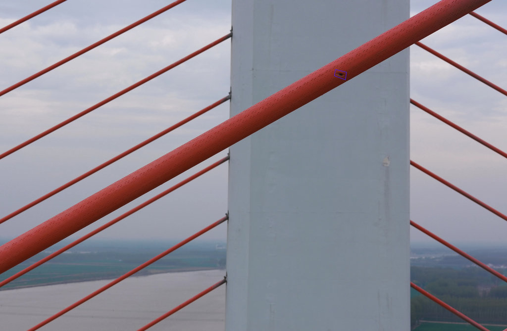
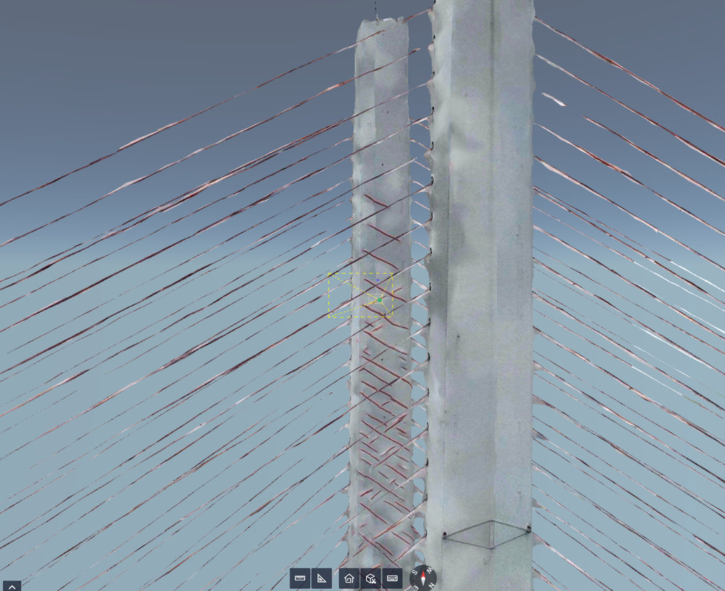
RIEBO’s AI defect recognition model processed the collected imagery to flag candidate defects on the cable sheath and pylon surfaces; each confirmed defect was then localized in 3D against the bridge digital twin, so that maintenance crews could navigate directly to the exact cable and pylon face rather than re-searching the structure on site.
RIEBO Inspection Management Platform
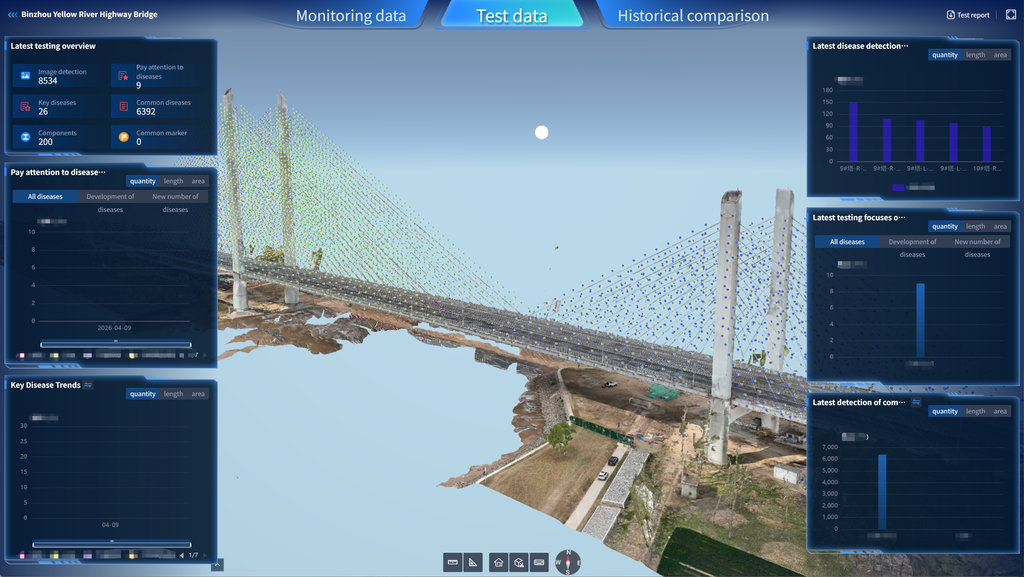
All imagery, AI results, 3D model and defect records were consolidated into the RIEBO inspection management platform, which indexed 200 bridge components and classified defects into common and key categories for follow-up maintenance planning.
Inspection Workflow
01. Site Reconnaissance and Airspace Coordination
The team first surveyed the site, identified available deck and riverbank take-off/landing points, and completed airspace and flight coordination before any flight.
02. Take-Off Points, RTK Setup and Perimeter Safety
RTK base stations and perimeter safety watches were set up at the deck and riverbank landing zones, so that every acquired image carried geotagged positioning and the flight envelope was kept clear of the driving lane.
03. Baseline 3D Model Acquisition
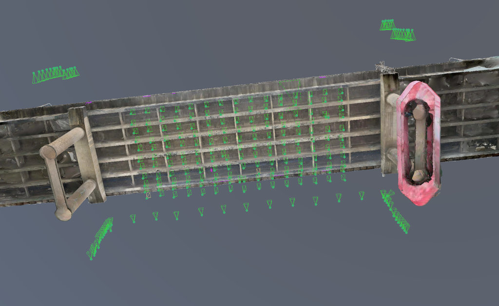
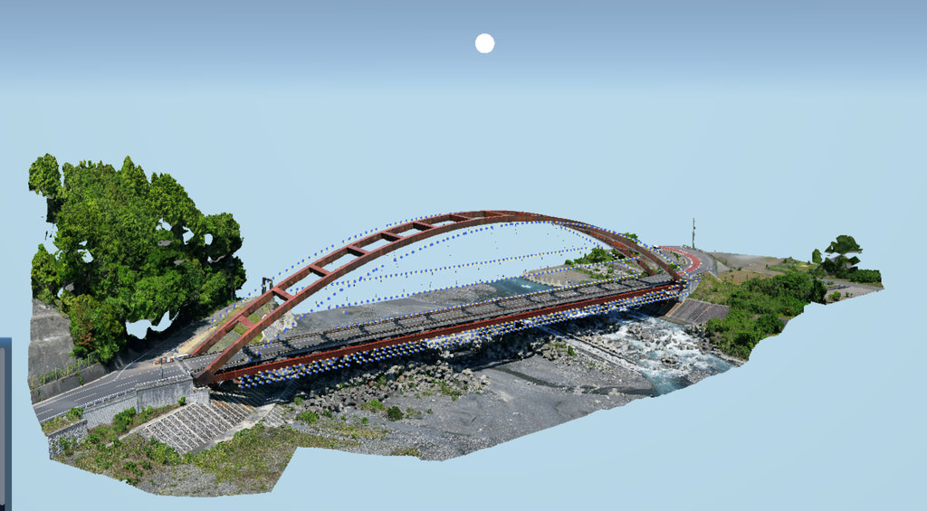
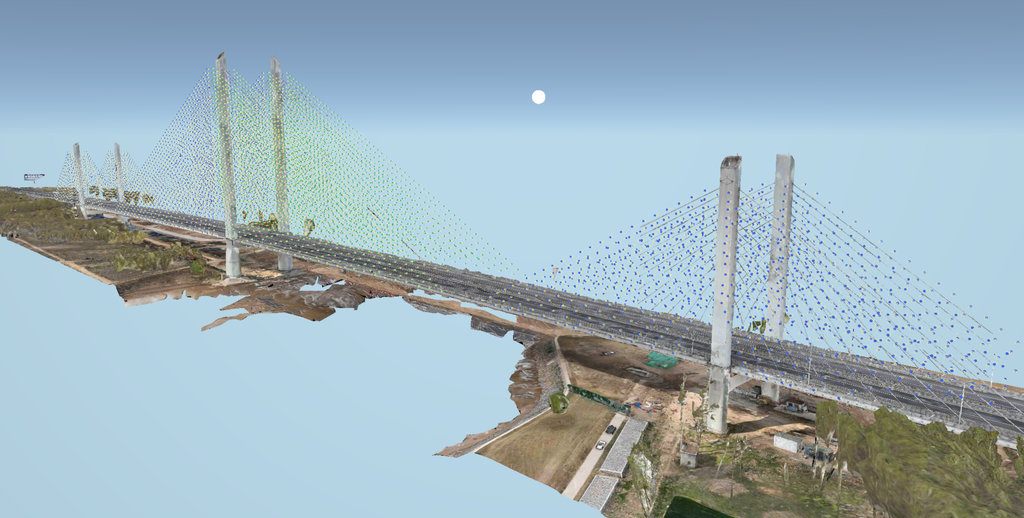
An initial mapping flight collected the bridge and surrounding riverbank geometry to build a baseline 3D model of the full structure, on which subsequent inspection routes and defect positions could be registered.
04. Zone-by-Zone Route Planning
Routes were planned per zone: pylon-orbit routes for the tower shafts, follow-the-cable routes for each stay cable, and deck-bottom routes under the main span. Waypoints and stand-off distances were tuned to the pylon height and the crossed-cable geometry.
05. Autonomous Data Acquisition with Targeted Re-Fly
The UAV flew the planned routes autonomously, capturing high-definition imagery of the pylon shafts, cable conduits and stay cables. Suspected defects were revisited on site for targeted close-up re-shoots before the team demobilized.
06. Point Cloud Reconstruction and AI Defect Annotation
Post-processing reconstructed the point cloud from the acquired imagery, and the RIEBO AI defect recognition model annotated candidate defects across the dataset.
07. Archive and Maintenance Recommendations
Inspection results were archived in the RIEBO platform, and maintenance recommendations were issued for the owner’s routine periodic-inspection and follow-up maintenance workflow.
Technology & Equipment
UAV Platform
DJI M400 RTK, used as the third-party flight platform for autonomous close-range bridge data acquisition.
Inspection Camera
SF10 inspection camera, capturing the high-definition still imagery used for surface defect screening on the cable sheath and pylon surfaces.
Navigation / Positioning
RTK positioning was used throughout, so that every image and every defect record carried a georeferenced position usable for 3D registration.
LiDAR
Onboard LiDAR was deployed specifically for rapid stand-off distance and focus locking on the target stay cable, mitigating crossed-cable occlusion and river-gust wind effects.
AI Analysis
RIEBO’s proprietary AI defect recognition processed the image dataset to flag surface defects — including stay-cable sheath scoring / abrasion as the representative defect type — before inspector review. Candidate defects were then classified into common and key categories;
Inspection Management Platform
The RIEBO inspection management platform indexed the 200 inspected components, held the 3D digital twin, and consolidated defect counts, trends and follow-up lists for the owner’s maintenance team.
From Inspection Images to Structured Data
The project transformed raw UAV inspection imagery into a structured inspection dataset through the following workflow:
Image Acquisition → Data Processing → AI Analysis → Inspector Review → Defect Localization → Inspection Records
Original Inspection Image
AI Detection Result
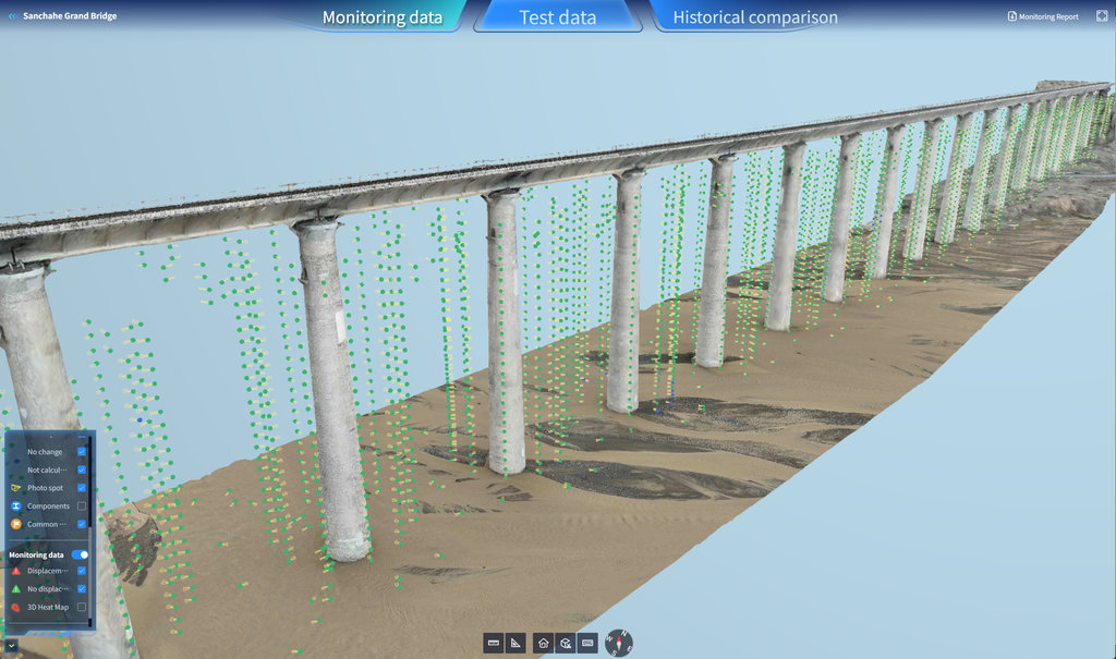
3D / Digital Twin Result
Defect Localization in 3D
Inspection Platform
Inspection Results
Single Field Day, No Traffic Closure
The full high-definition inspection of the pylons, stay cables and anchorage zones was completed in one field day, with no lane closure and no interruption to highway traffic — eliminating the traffic-management cost and safety exposure of rope access and under-bridge vehicles.
8,534 Geotagged High-Definition Images
The mission captured 8,534 high-definition images, each RTK-georeferenced and registered to the 3D model, providing a full-coverage visual baseline for the periodic inspection.
6,427 Surface Defects Screened, 26 Flagged as Key
AI-assisted screening followed by inspector review identified 6,427 surface defects across the inspected components — 6,392 common defects and 26 key defects — including stay-cable sheath scoring/abrasion as the representative defect type, giving the owner a prioritized maintenance list rather than a blank re-survey.
Defect-Level 3D Localization on a Digital Twin
Every confirmed defect was localized in 3D on the bridge digital twin and indexed against 200 components in the management platform, enabling targeted re-checks and trend comparison against future inspections.
Project Data
| Metric | Result |
| Bridge Components Inspected | 200 (pylons, stay cables, deck anchorage zones) |
| Images Collected | 8,534 high-definition images |
| 3D Model Coverage | Full-bridge photo-realistic digital twin |
| Potential Defects Identified | 6,427 (6,392 common + 26 key) |
| Inspection Duration | 1 field day |
| Traffic Closure | None |
Project Benefits
Operational Benefits
- High-altitude, waterside pylon and cable inspection completed without rope access or under-bridge vehicles, reducing inspector exposure to high work over water.
- No lane closure or traffic control was required during data acquisition, eliminating the traffic-management cost of working on a busy highway river crossing.
- Pylon-rear, anchorage-zone and behind-cable areas that were blind to telescope inspection were brought into full visual coverage.
Data Benefits
- 8,534 RTK-georeferenced images form a reusable, spatially registered visual baseline for future periodic inspections.
- 6,427 defects are classified by severity (6,392 common / 26 key) and localized to the specific cable, pylon face and component, rather than recorded as qualitative field notes.
- A photo-realistic 3D digital twin supports side-by-side comparison against future inspection campaigns.
Inspection Management Benefits
- Results are consolidated in the RIEBO platform across 200 components, with follow-up and “pay attention to” defect lists ready for maintenance planning.
- Defect-level 3D coordinates let maintenance crews navigate directly to a defect for re-check, avoiding a full re-survey on site.
- The workflow supports low-cost, safe, full-coverage routine screening of corrosion, cracks and sheath damage for ongoing highway operation.
Key Takeaways
This project shows how an autonomous UAV mission — using a DJI M400 RTK platform, LiDAR-assisted cable focusing, and RIEBO’s AI defect recognition and 3D digital twin — can inspect the pylons, stay cables and anchorage zones of a long-span cable-stayed highway river bridge in a single field day, with no traffic closure and no rope access.
Across the fan of stay cables, the dataset produced 8,534 geotagged images and 6,427 classified defects, each localized on the digital twin for targeted follow-up. The approach is directly transferable to other cable-supported bridges where high-altitude waterside access, heavy traffic and crossed-cable occlusion make conventional inspection slow, risky and incomplete.
Related RIEBO Solutions
- Drone Bridge Inspection Solution (end-to-end UAV data acquisition, AI detection and digital twin)
- Bridge Digital Twin and 3D Defect Localization
- RIEBO Inspection Management Platform (component indexing, defect classification, trend comparison)
Have a Bridge Inspection Project?
Tell us about your bridge, inspection scope and project requirements.
Or explore the complete RIEBO Drone Bridge Inspection Solution.