Project Snapshot
| Item | Details |
| Project | Drone Bridge Inspection Demonstration — OKouchi Bridge |
| Location | Shizuoka, Japan |
| Bridge Type | Steel single-span Nielsen-Lohse tied arch bridge, 75° skew |
| Inspection Scope | Full bridge appearance — arch ribs, crossed diagonal hangers, hanger anchorage nodes, bearings, arch springing, arch foundations, welds, high-strength bolts, coating |
| Inspection Method | UAV close-range photography + photogrammetric 3D modeling |
| Key Technologies | Autonomous flight planning, AI-assisted defect detection, 3D digital twin, 3D defect localization |
| Project Period | May 2024 · 1 field day |
Project Overview
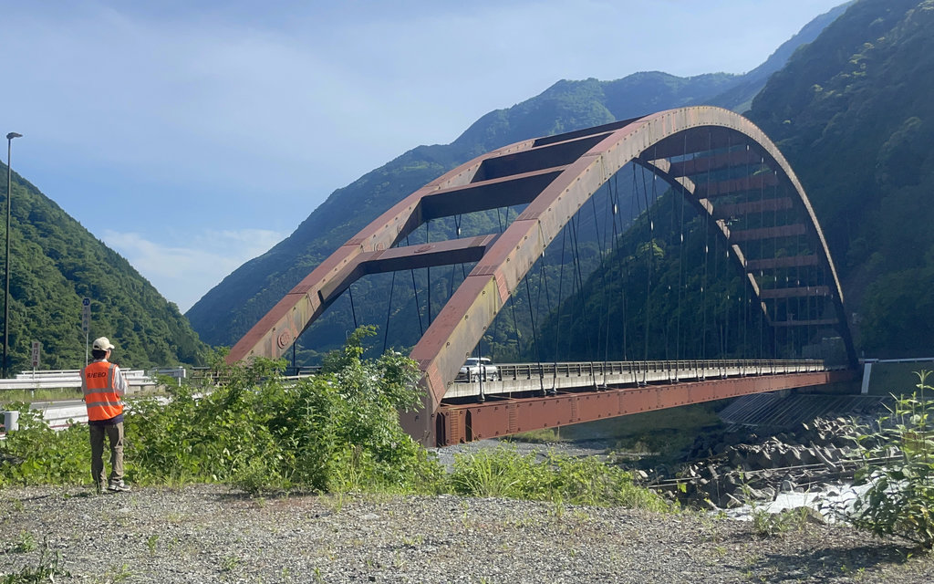
OKouchi Bridge is a 165.5m long, 8m wide steel single-span arch bridge of the Nielsen-Lohse type, in which inclined hangers cross each other between the arch rib and the deck girder. The bridge is a heavily skewed structure, built at a 75° skew angle rather than crossing square-on. Its deck, painted in a distinctive deep red, is only 8 m wide. The combination of the severe skew, crossed diagonal hangers and closely spaced steel members leaves the structure with many enclosed angles, shadowed faces and stress-concentrated joints: the skew induces torsional forces at the arch springing, and bearing reactions are unevenly distributed between the obtuse and acute corners.
The bridge owner required its regular inspection to cover the full bridge appearance—including the arch ribs, the crossed diagonal hangers with their anchor heads and crossing friction zones, the hanger anchorage nodes on the main girder, the skewed bearings and the arch springing—and to record the condition of the coating, welds, high-strength bolts and corrosion-susceptible details.
Traditional inspection relied on ground observation from the deck and banks using high-magnification telescopes and telephoto cameras, on under-bridge inspection vehicles that need lane closures and deck space, and on rope-access crews working from the arch—supplemented by targeted instrument checks such as cable-force measurement and coating-thickness gauging. From ground level, the 75° skew and mutually obscuring hangers hide the backs of members, hanger roots and node welds, so routine patrols can only flag large-scale coating loss and obvious deformation; fine corrosion and hairline cracks remain invisible. Close-range, reliable records of the most fatigue-prone and corrosion-prone details were difficult, slow and costly to obtain.
The inspection focused on these specific bridge components, with the primary objective of producing high-resolution, location-stable records that could be repeated in future cycles and compared over time. Due to the narrow deck, the river crossing, the skew geometry and the cost of traffic disruption, the project required a method that could collect reliable inspection data from the hardest-to-reach areas without extended lane closures or personnel working at height.
Inspection Challenges
Challenge 01 — Hard-to-Reach Steel Components
The crossed diagonal hangers—including their anchor heads, anchorage plates, sheathing, crossing friction zones and force-critical sections—are the hardest parts of the bridge to inspect. At a 75° skew, the mutually crossing hangers obscure one another, hiding the backs of members, hanger roots and node welds from any ground viewpoint. Arch ribs, arch springing and the hanger anchorage nodes on the main girder (typical fatigue sources) add further difficult-to-access areas. Steel dead angles are everywhere, and a ground-based camera simply cannot produce inspection-grade records of them.
Challenge 02 — Skewed Geometry and Stress Concentration
At a 75° skew, the arch rib and arch springing are subject to pronounced torsional and concentrated loads—the obtuse-side arch springing carries the highest stress. Bearing reactions are likewise unevenly distributed: obtuse-corner bearings are over-pressured while acute-corner bearings risk becoming unloaded. These are exactly the points where the owner wanted reliable visual evidence, yet a simple top-down flight cannot photograph such geometry at a consistent standoff distance. Every inspection point had to be approached with a flight line matched to the member’s orientation.
Challenge 03 — Traffic and Site Constraints
An under-bridge inspection vehicle on the 8m’s wide deck would occupy nearly half to the full carriageway and require lane closures; its basket also struggles to enter the gaps between crossed hangers and the dead corners behind the arch ribs. Rope access is the only conventional method that can reach the backs of hangers and nodes, but it is slow, carries high fall risk, and cannot be performed in strong wind—a practical limit given the wind conditions on the working day. The skew geometry also complicates rope anchor planning, and ropes can be abraded by steel members. The river crossing limits personnel access beneath the span, and weather placed additional constraints on safe flight operations.
Challenge 04 — Comparability for Deterioration Tracking
Routine manual inspection produces fragmented records that are difficult to compare between cycles. The owner wanted imagery tied to stable 3D positions so that future inspections could be matched against a baseline and changes in corrosion and coating condition assessed over time.
RIEBO’s Drone Bridge Inspection Solution
To address these requirements, RIEBO deployed its Drone Bridge Inspection Solution, combining autonomous flight planning with a high-resolution RIEBO SF10 inspection camera on a DJI M400 RTK platform, photogrammetric 3D modeling, and AI-assisted defect detection managed on RIEBO’s self-developed inspection management platform.
Autonomous Flight Planning for Complex Steel Geometry
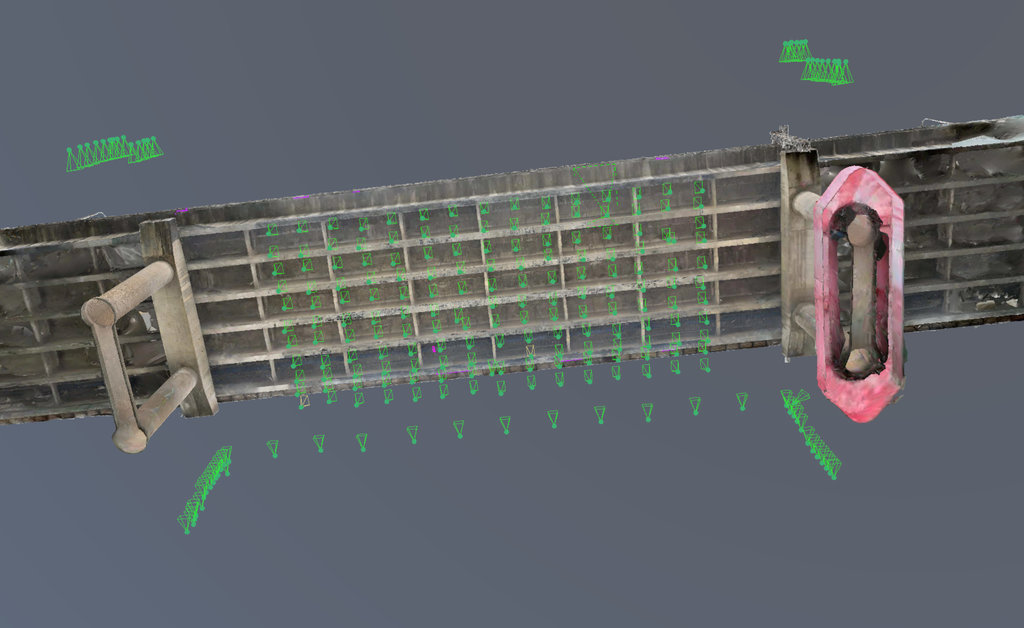
With crossed diagonal hangers and skew geometry, generic flight patterns miss the dead angles. RIEBO imported the bridge’s baseline data, flew an initial coarse pass to build the first 3D model and point cloud, then planned targeted autonomous routes for each hard-to-reach component—arch ribs, diagonal hangers, anchorage nodes, bearings and arch springing. Manual supplementary flights covered the remaining complex dead corners. The result was complete, repeatable coverage with consistent image overlap, captured on automated routes wherever the geometry allowed.
High-Resolution Aerial Imaging with the RIEBO SF10
The RIEBO SF10 inspection camera, mounted on the DJI M400 RTK, captured 985 high-resolution images during the single field day. This gave inspectors close-range visual records of the coating, welds, high-strength bolts and corrosion on the crossed diagonal hangers and arch ribs—details that ground observation, inspection vehicles and rope-access surveys could not deliver at this completeness in the same time.
3D Digital Twin and AI-Assisted Defect Detection
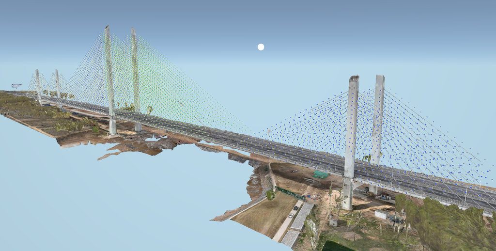
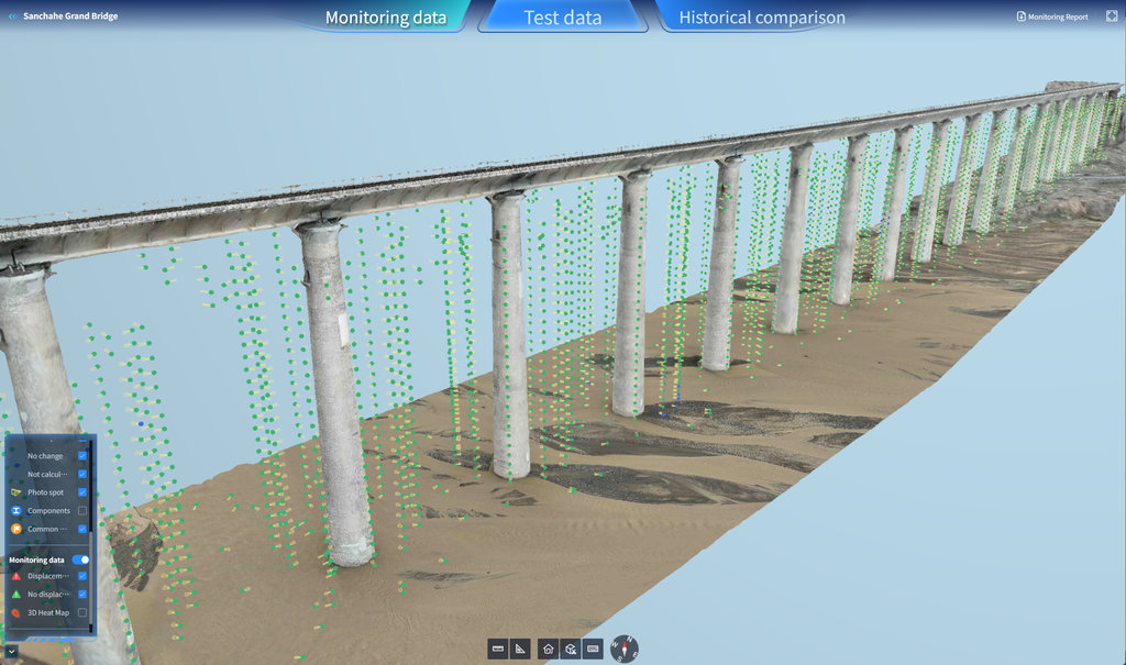
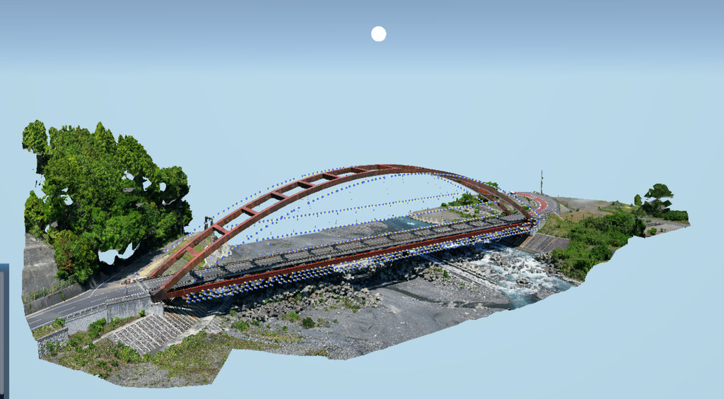
Photogrammetry turned the imagery into a 3D model and digital twin of the bridge, updated during the project as data was processed. RIEBO’s AI performed initial detection of corrosion, coating peeling, sheath damage, weld cracks and bolt anomalies; bridge engineers then reviewed every finding, localized and graded it on the 3D model, and compared it with previous inspection records. Defect data became location-aware—attached to the structure—rather than a folder of unpositioned photographs.
Self-Developed Inspection Management Platform
All 985 images, video, the 3D model and the defect records were managed on RIEBO’s self-developed inspection management platform, producing a structured inspection dataset, defect localization data and an inspection report that the client could use directly for reporting to its supervisory authority.
Inspection Workflow
01. Inspection Planning
Site survey and airspace filing, followed by launch-point layout on the deck, traffic warning and equipment checks before the first flight.
02. 3D Modeling / Route Planning
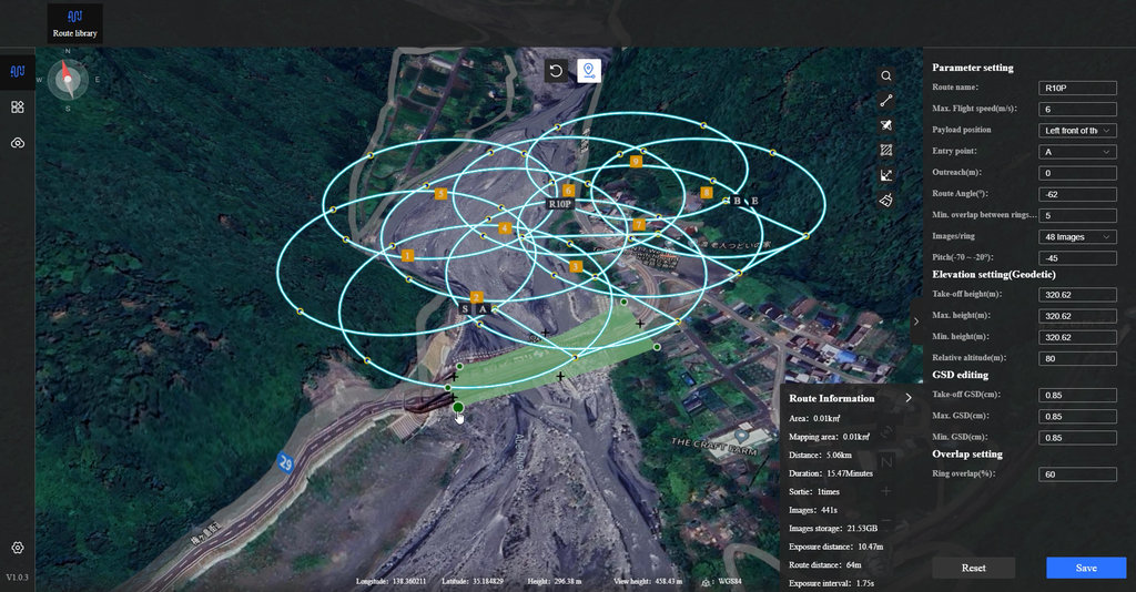
Bridge baseline data import, then an initial coarse flight to capture the first 3D model and point cloud, followed by targeted autonomous route planning for the crossed diagonal hangers, arch ribs, arch springing and anchorage nodes.
03. UAV Data Acquisition
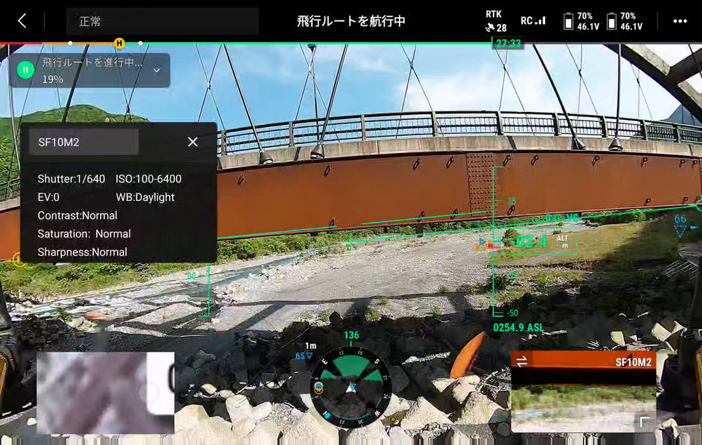
The DJI M400 RTK with the RIEBO SF10 camera flew automated routes over each component—arch ribs, diagonal hangers, main girder anchorage areas, bearings and arch springing—with manual supplementary flights for complex dead corners. Strong-wind conditions on site were managed within safe operating limits.
04. Data Processing
On-site data quality checks verified coverage, missing areas were re-flown, and data preprocessing updated the 3D model.
05. AI-Assisted Defect Detection
RIEBO’s AI pre-screened the imagery for corrosion, coating peeling, sheath damage, weld cracks and bolt anomalies.
06. Defect Localization & Visualization
Bridge engineers reviewed every AI finding, localized and graded defects on the 3D model, and compared results with previous inspection cycles for defect development analysis.
07. Inspection Reporting
Inspection records were archived on the platform, and the inspection report with maintenance recommendations was delivered to the client.
From Inspection Images to Structured Data
The project transformed raw UAV inspection imagery into a structured inspection dataset through the following workflow:
Image Acquisition → Data Processing → AI Analysis → Inspector Review → Defect Localization → Inspection Records
Original Inspection Image
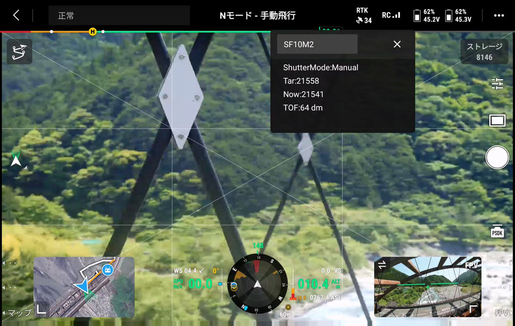
AI Detection Result
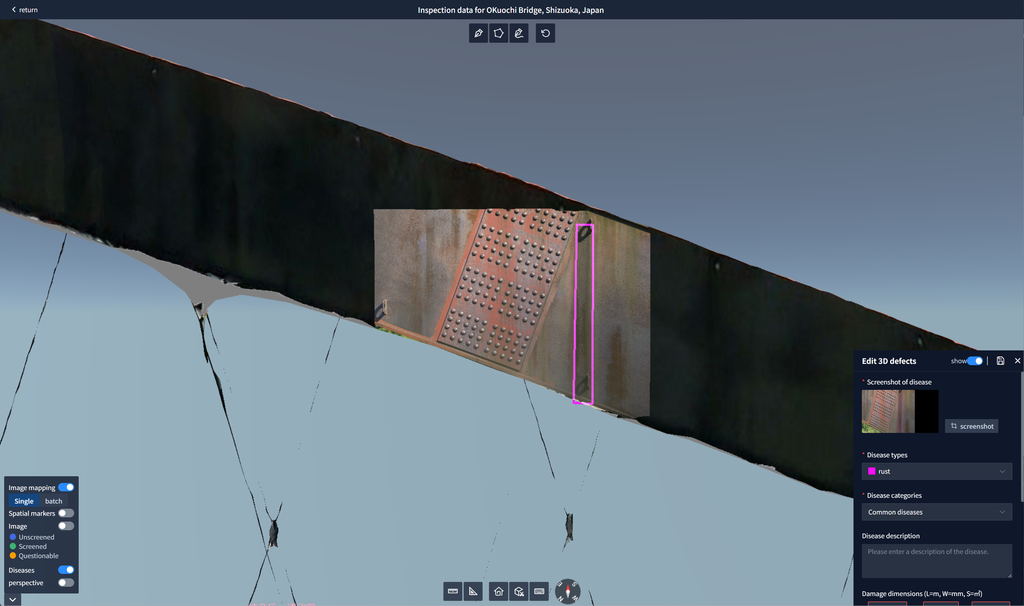
3D / Digital Twin Result
Inspection Platform
Inspection Results
Full Coverage of the Hardest-to-Reach Areas
985 high-resolution images covered the arch ribs, crossed diagonal hangers, anchorage nodes, bearings and arch springing in one field day—components that normally require bridge inspection vehicles or rope-access work.
No Bridge Inspection Vehicle, No Rope-Access Crew
The entire inspection was performed with the drone, with minimal traffic disruption on the 8 m deck and no personnel working at height over the river.
3D Baseline for Long-Term Comparison
A 3D model and digital twin of the bridge were produced, giving the client a location-stable baseline to which future inspection cycles can be matched for defect development analysis.
AI + Engineer Review Workflow
AI pre-screened the imagery for corrosion, coating peeling, sheath damage, weld cracks and bolt anomalies; every finding was reviewed, localized and graded by bridge engineers before entering the inspection record.
Client-Ready Data Package
All imagery, video, 3D model, defect annotations and the inspection report were consolidated on one platform, and the client used the results for reporting to its supervisory authority.
Project Data
| Metric | Result |
| Bridge Components Inspected | Arch ribs, crossed diagonal hangers, anchorage nodes, bearings, arch springing, arch foundations, welds, high-strength bolts, coating |
| Inspection Area | Bridge appearance |
| Images Collected | 985 |
| 3D Model Coverage | Full-span 3D model / digital twin produced |
| Potential Defects Identified | These are common diseases and cannot be disclosed due to customer privacy |
| Inspection Duration | 1 field day (May 2024) |
| Other Verified Metric | No bridge inspection vehicle or rope-access crew required |
Project Benefits
Operational Benefits
- Inspection completed in a single field day without bridge inspection vehicles or rope-access crews
- Minimal traffic disruption on an 8 m deck crossing a river
- No personnel working at height over water
Data Benefits
- 985 high-resolution images tied to a 3D model / digital twin
- Location-stable baseline for comparing future inspection cycles and tracking deterioration
- AI-assisted screening plus engineer review of every defect record
Inspection Management Benefits
- All records—images, video, 3D model, defect annotations, report—managed on one self-developed platform
- Ready-to-use data package for reporting to the supervisory authority
Key Takeaways
- Drone inspection made a skew-geometry tied arch bridge with crossed diagonal hangers fully inspectable in one field day—without a bridge inspection vehicle or rope-access crew.
- Combining autonomous route planning with a high-resolution camera produced 985 inspection-grade images of components that manual methods could not adequately cover in the same timeframe.
- Photogrammetric 3D modeling turned the imagery into a location-aware digital twin, creating a baseline for long-term deterioration tracking.
- AI-assisted detection, verified by bridge engineers, turned raw imagery into structured, graded defect records.
- The project demonstrates how a UAV bridge inspection approach with autonomous flight planning, close-range imaging and AI-assisted analysis can support regular inspection of a complex steel arch bridge while producing a structured, comparable 3D-referenced dataset.
Related RIEBO Solutions
Fully Automatic Route Planning for Intelligent Bridge Inspection