Project Snapshot
| Item | Details |
| Project | Drone Bridge Underside Inspection Demonstration — Yuzhang Bridge, Span 6 (client confidential) |
| Location | Nanchang, Jiangxi, China (crossing the Gan River) |
| Bridge Type | Prestressed concrete simply-supported T-beam bridge — 560.61 m long, 13.5 m deck width, 16 spans / 5 continuous units (4×30 m + 3×42 m + 3×42 m + 3×30 m + 3×42 m), opened 1990 |
| Inspection Scope | Span 6 underside: T-beam soffit, girder webs, diaphragm bottoms; concrete surface defects (cracks, spalling, exposed rebar, corrosion) |
| Inspection Method | UAV close-range photography + photogrammetric / LiDAR-assisted 3D modeling |
| Key Technologies | Autonomous flight planning, under-bridge navigation in weak-GNSS conditions, AI-assisted defect detection, 3D digital twin, 3D defect localization |
| Project Period | May 19, 2026 · 1 field day |
Project Overview
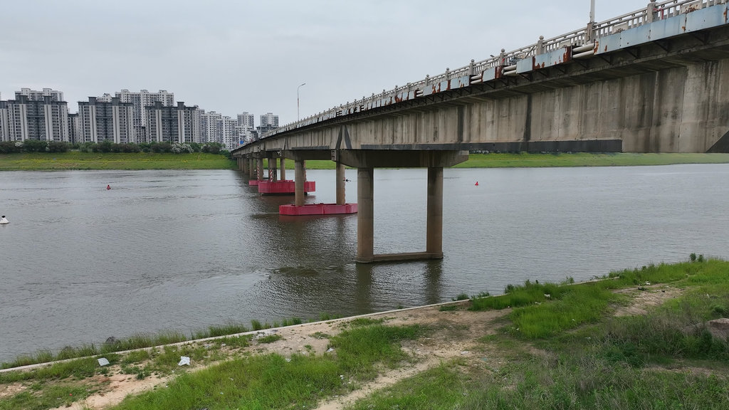
Yuzhang Bridge carries an important commuting corridor in the north of Nanchang across the Gan River. Opened in 1990 and now more than 35 years in service, it is a prestressed concrete simply-supported T-beam bridge with 16 spans arranged in five continuous units and a total length of 560.61 m. Like all highway bridges in China, it is subject to regular inspection under the national bridge maintenance code. Its condition—cracks, spalling, exposed rebar and corrosion—must be monitored on the girder soffits and webs, the parts of a T-beam bridge that matter most for concrete and prestressing condition, yet sit high above the water.
The inspection focused on Span 6, one of the bridge’s 42 m simply-supported spans, with the primary objective of producing reliable, close-range inspection records of the T-beam soffit, girder webs and diaphragm bottoms, and demonstrating a digital inspection workflow that could become the bridge’s routine inspection baseline.
Due to the river crossing, the height of the girder underside above the water, the weak GNSS environment under the concrete deck and the cost of traffic disruption, the project required a method that could collect reliable inspection data from the hardest-to-reach areas without lane closures or personnel working at height over the river.
Inspection Challenges
Challenge 01 — Girder Bottoms and Diaphragm Bottoms Hanging High Over the River
The main girder soffit and the diaphragm bottoms of Span 6 are suspended directly above the Gan River, far above the water surface. A bridge inspection vehicle basket can only reach part of the underside: in the river wind the basket sways, and the corners, the back sides of the diaphragms and the joints between girders remain out of reach. Small cracks, efflorescence and concrete spalling in these hidden zones are invisible from the deck or from the riverbank at any practical working distance—leaving exactly the load-critical zones of the T-beam structure without inspection-grade records.
Challenge 02 — Weak GNSS and Confined Space Under the Concrete Deck
Underneath the concrete deck, satellite signals are weak and frequently blocked, so standard GNSS-guided flight is unreliable. The confined under-bridge space, combined with strong river wind and the light rain on the working day, makes positioning and safe navigation the first problem to solve before a single image can be captured.
Challenge 03 — Traffic Disruption and Safety Cost of Conventional Access
The conventional approach—a bridge inspection vehicle with baskets, supplemented by scaffolding, boat-based visual checks, diving probes and long-distance telescope observation—requires lane occupation and traffic control on a busy commuting corridor, carries fall and over-water safety risks for personnel, and produces a long workflow with many blind zones. Every lane closure translates directly into commuter delay and safety exposure.
Challenge 04 — No Digital Baseline for an Aging Structure
At more than 35 years old, the bridge needed a location-stable digital record of its condition. Conventional inspection output—fragmented photos and paper notes—is difficult to compare between cycles, making it hard to track how cracks, spalling and corrosion develop over time.
RIEBO’s Drone Bridge Inspection Solution
To address these requirements, RIEBO deployed its Drone Bridge Inspection Solution, combining autonomous flight planning, under-bridge navigation in weak-GNSS conditions, a high-resolution RIEBO SF10 inspection camera on a DJI M400 RTK platform, AI-assisted defect detection and 3D digital twin production, all managed on RIEBO’s self-developed inspection management platform.
Autonomous Route Planning and Under-Bridge Navigation
RIEBO planned the inspection with AeroMap Pro route planning software and flew automated full-coverage routes under the deck, with manual supplementary flights for the blind spots the automated routes could not reach. For positioning, the UAV carried the RIEBO RPX high-precision inertial navigation module together with LiDAR, allowing it to navigate reliably under the concrete deck where GNSS signals are weak—the difference between a stable, repeatable acquisition pass and a flight that drifts beneath the bridge.
High-Resolution Close-Range Imaging with the RIEBO SF10
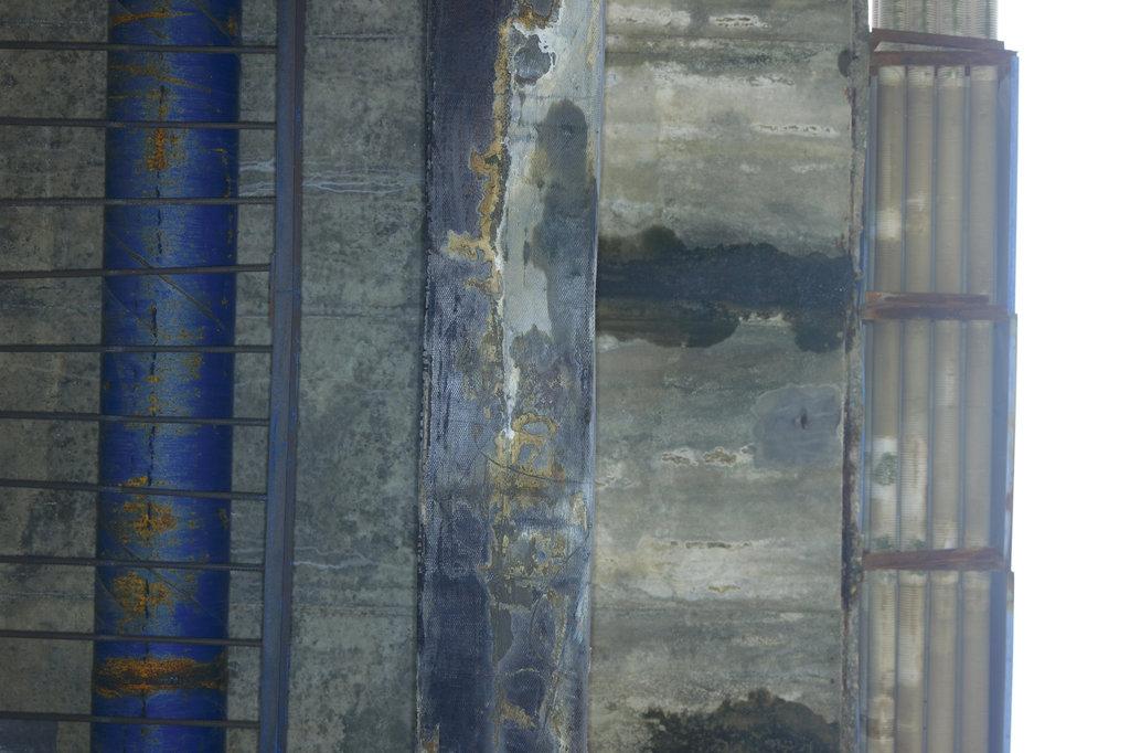
The RIEBO SF10 inspection camera, mounted on the DJI M400 RTK, captured 233 high-resolution images of Span 6 during the single field day, operating within safe limits even in light rain. The close-range standoff distance kept cracks, spalling, exposed rebar and corrosion visible at inspection grade—the level of detail that bank-side telescope observation and basket viewing cannot deliver.
AI-Assisted Defect Detection with Engineer Verification
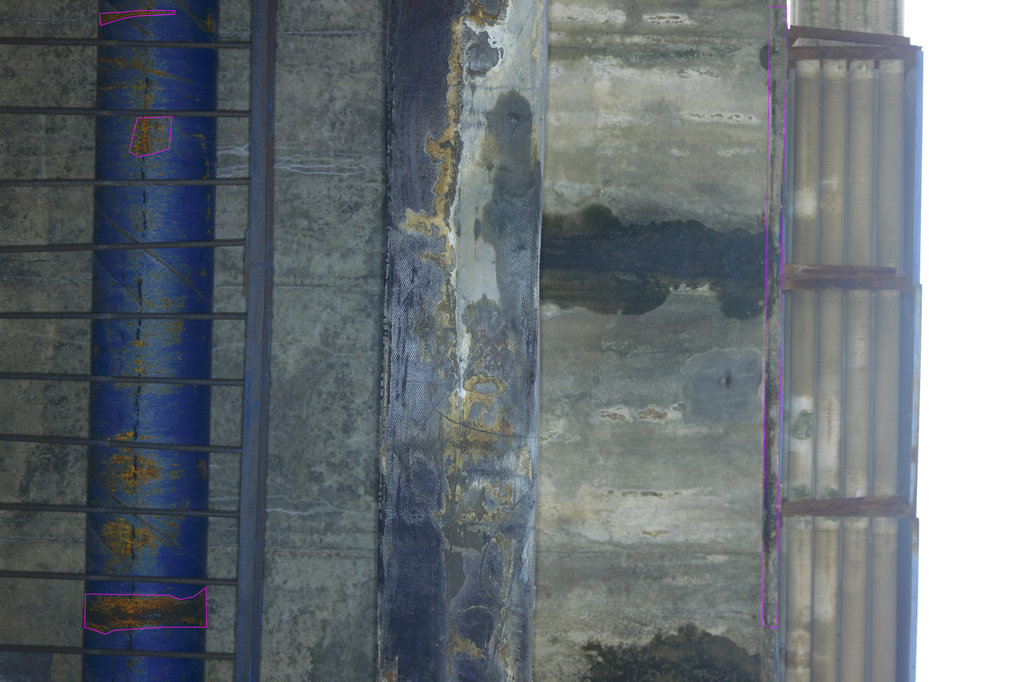
RIEBO’s AI models pre-screened the imagery for four defect categories—cracks, concrete spalling, exposed rebar and corrosion—and every finding was reviewed, localized and graded by bridge engineers before entering the inspection record. AI is used as a screening layer, not as the final verdict: the output is a defect list the owner can act on.
3D Digital Twin and Defect Localization
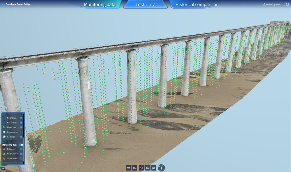
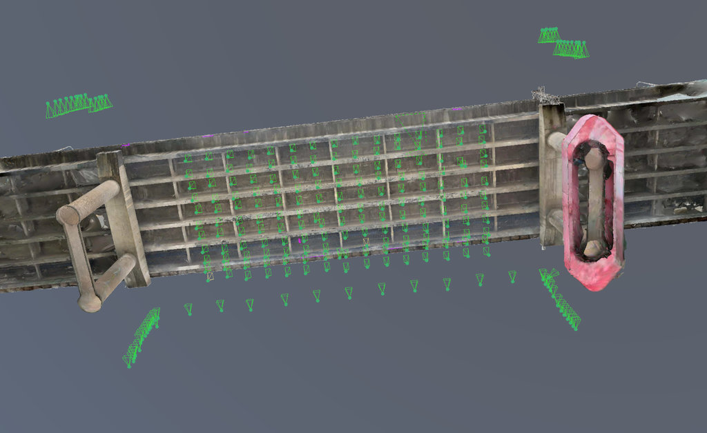
Close-range imagery and point-cloud data were processed into a 3D model of Span 6 with image acquisition points. Defects were then localized on the model, turning a folder of unpositioned photographs into location-aware inspection records tied to the structure—the starting point of a digital archive for the 1990 bridge.
Inspection Workflow
01. Inspection Planning
Airspace filing, site survey, launch-point layout on the riverbank and equipment checks before the first flight.
02. 3D Modeling / Route Planning
Bridge baseline data import, an initial coarse pass to establish the under-deck geometry, then targeted autonomous route planning with AeroMap Pro for full underside coverage of Span 6.
03. UAV Data Acquisition
The DJI M400 RTK with the RIEBO SF10 flew automated routes under the deck, with manual supplementary flights covering the blind corners, diaphragms and joints. Weak GNSS was handled by the RIEBO RPX inertial navigation module and LiDAR; the light rain was managed within safe operating limits.
04. Data Processing
On-site quality checks verified coverage of each component, missing areas were re-flown, and the data were backed up and processed into the 3D model.
05. AI-Assisted Defect Detection
RIEBO’s AI pre-screened the 233 images for cracks, spalling, exposed rebar and corrosion.
06. Defect Localization & Visualization
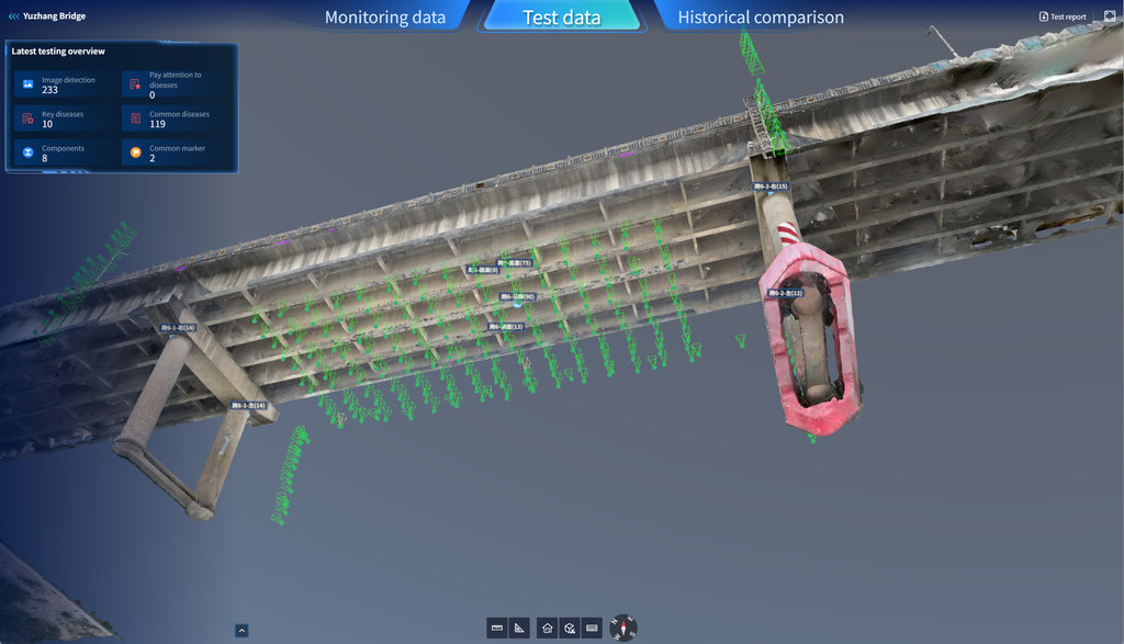
Bridge engineers reviewed every AI finding, localized and graded the defects on the 3D model, and flagged the 10 key defects requiring priority attention.
07. Inspection Reporting
All records—images, video, 3D model, defect annotations and the inspection report—were consolidated on RIEBO’s platform, and the client used the dataset for reporting to its supervisory authority.
Technology & Equipment
UAV Platform
DJI M400 RTK (third-party platform)—RTK positioning and obstacle perception suited to confined under-bridge work. [Detailed configuration XX]
Inspection Camera
RIEBO SF10 inspection camera (self-developed)—high-resolution close-range imaging for concrete surface defects. [Specifications XX]
Navigation / Positioning
RIEBO RPX high-precision inertial navigation module plus LiDAR for reliable positioning in the weak-GNSS under-deck environment.
AI Analysis
Self-developed AI models performed initial recognition of cracks, spalling, exposed rebar and corrosion; every AI finding was reviewed by bridge engineers—AI output is used as a screening layer, not as the final verdict.
Inspection Management Platform
RIEBO’s self-developed smart inspection management platform managed the 233 images, defect records, 3D model and report, organizing the data by structural component (8 component groups of Span 6).
From Inspection Images to Structured Data
The project transformed raw UAV inspection imagery into a structured inspection dataset through the following workflow:
Image Acquisition → Data Processing → AI Analysis → Inspector Review → Defect Localization → Inspection Records
Original Inspection Image
AI Detection Result
3D / Digital Twin Result
Inspection Platform
Field Operation
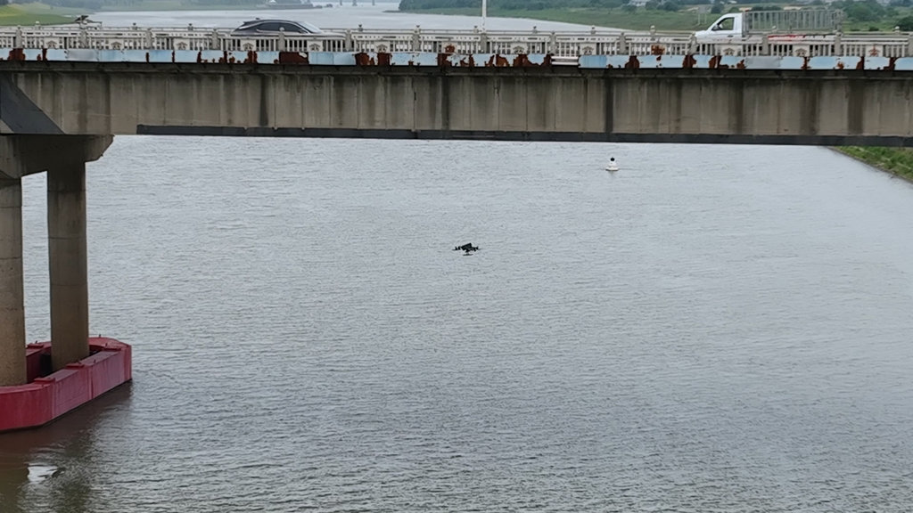
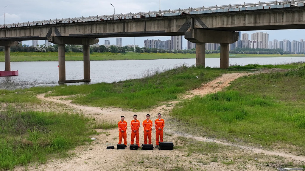
Inspection Results
Complete Underside Coverage of the Hardest-to-Reach Area
233 high-resolution images covered the Span 6 T-beam soffit, girder webs and diaphragm bottoms in one field day—the components that normally require a bridge inspection vehicle basket and personnel working at height over the river.
No Bridge Inspection Vehicle, No Traffic Closure
The operation was conducted from the riverbank: no lane closure, no traffic control and no personnel at height over water. Commuter traffic on this north-Nanchang corridor continued normally during the inspection.
129 Defects Identified, 10 Key Defects Flagged
AI screening plus engineer review identified 129 defects on Span 6—67 cracks, 36 exposed rebar, 22 corrosion and 4 spalling—of which 10 were flagged as key defects for priority follow-up.
Digital Baseline for an Aging Structure
The 3D digital twin with image acquisition points and defect localization gives the 1990 bridge a location-stable digital record, providing the baseline that future inspection cycles can be matched against for deterioration tracking.
Client-Ready Dataset
All imagery, video, 3D model, defect annotations and the inspection report were consolidated on one platform, and the client used the results for reporting to its supervisory authority.
Project Benefits
Operational Benefits
- Underside inspection completed in a single field day without a bridge inspection vehicle
- No lane closure or traffic control on a busy commuting corridor; no personnel working at height over the river
- Acquisition tolerated light-rain conditions within safe operating limits
Data Benefits
- 233 high-resolution images georeferenced to a 3D digital twin of the span
- 129 defects across four categories structured into records, with 10 key defects prioritized
- Location-stable digital baseline for tracking deterioration of a 35+ year-old structure across inspection cycles
Inspection Management Benefits
- One self-developed platform for images, video, 3D model, defect annotations and reporting
- Client-ready dataset used directly for reporting to the supervisory authority
Key Takeaways
- Drone underside inspection made the most inaccessible part of an old river-crossing T-beam bridge—the girder soffits and diaphragm bottoms above the Gan River—fully inspectable in one field day, without a bridge inspection vehicle or lane closures.
- Autonomous route planning and under-bridge navigation solved the weak-GNSS environment under the concrete deck, keeping acquisition stable even in light rain.
- AI-assisted detection with engineer verification identified 129 defects across four categories on a single span and flagged the 10 that need attention first.
- The 3D digital twin created a location-stable digital archive for a 1990 bridge, enabling change tracking in future cycles.
- The project demonstrates how UAV bridge inspection with autonomous route planning, close-range imaging and AI-assisted analysis can support regular inspection of concrete T-beam highway bridges while producing a structured, comparable dataset.
Related RIEBO Solutions
- Drone Bridge Inspection Solution (end-to-end UAV data acquisition, AI detection and digital twin)
- Bridge Digital Twin and 3D Defect Localization
- RIEBO Inspection Management Platform (component indexing, defect classification, trend comparison)
Related Questions
- Can drones inspect bridge undersides?
- How accurate is drone bridge inspection?
- How does AI defect detection work for bridge inspection?
- How is bridge inspection data managed?
Have a Bridge Inspection Project?
Tell us about your bridge, inspection scope and project requirements.
Or explore the complete RIEBO Drone Bridge Inspection Solution.